CAUTION
If input voltages (measured with the SkyTracker in full operation with all lights
andmotionon)arefoundtobeBELOWtheminimumlevelsspeciedinsec-
tion 3.1, damage to components may result and in particular the motion motor
may burn out. If voltages are found to be below the minimum levels, DO NOT
OPERATE THE SKYTRACKER. Components damaged from low voltage
operation will NOT be replaced under warranty. Similarly, if any other com-
ponents fail (including the xenon bulb) from over-voltage operation, they will
NOT be replaced under warranty.
NOTE: In certain areas 208 volts AC (rather than 220/240 volts) is the “nor-
mal” input voltage. Although SkyTrackers will operate on 208 volt input, the
brightness and overall performance will be less than normal unless the input
voltage adjustment taps are changed to compensate for this normal 10%
reduction in input voltage. Also, in some instances where current draw of the
SkyTracker is causing input circuit breakers to “trip,” or if portable generators
are “lugging down” and causing them to deliver less than normal input volt-
age, a downward adjustment of the taps to lower the lamp output will some-
times cure the problem.
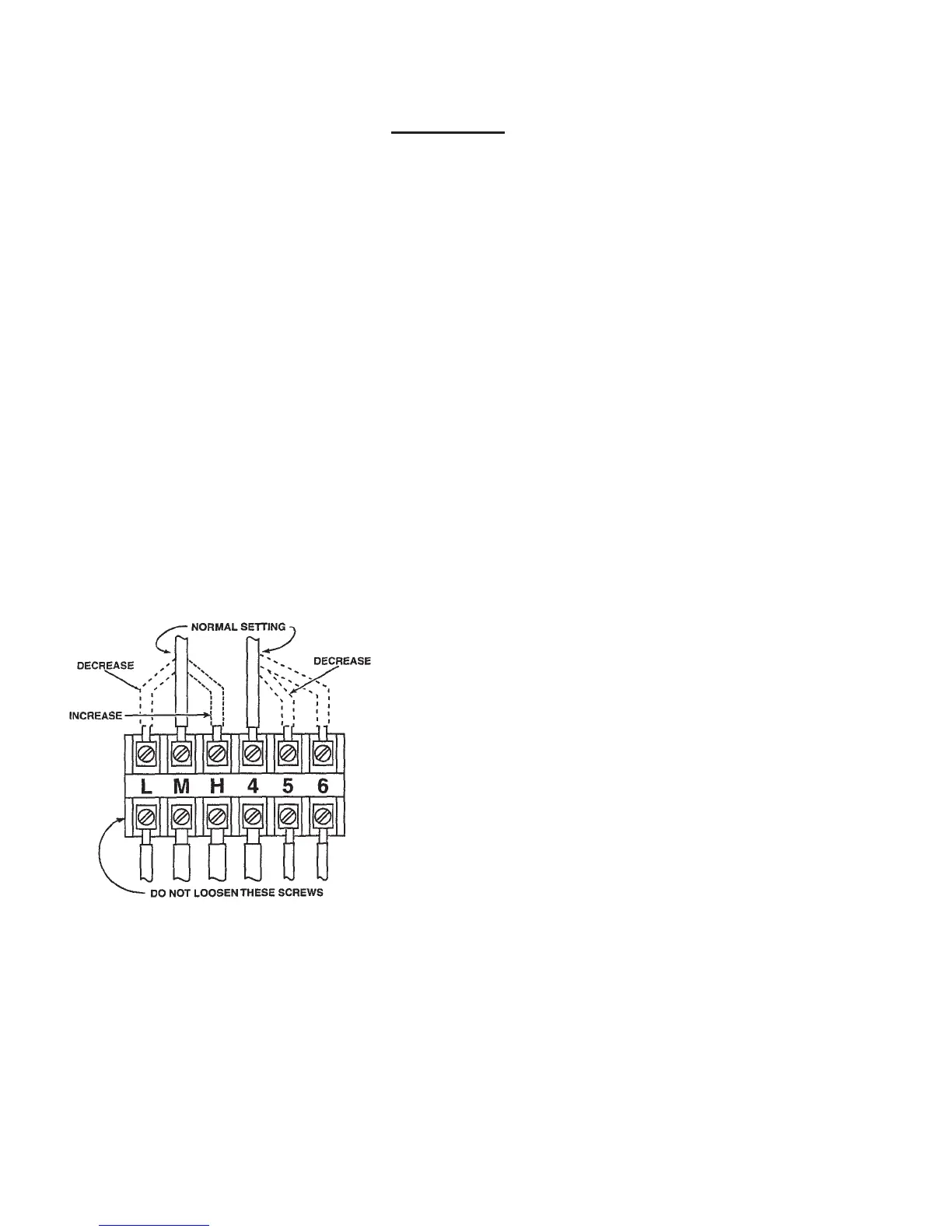
SINGLE PHASE ADJUSTMENT: 2 kW (240 Volt)
VOLTAGE ADJUSTMENT TAPS
(Single Phase)
FIGURE 5
A Voltage Adjustment Terminal Board is lo-
cated on the top of each power supply and the
various taps, or wire positions, are shown in
Figure5.ThetapsareidentiedasLow(L),
Medium (M), High (H), 4, 5, and 6.
Changing the letter taps (L, M, H) has a
smaller,“netuning”effect.Changingthe
number taps (4, 5, 6) has a greater effect.
The highest setting (H-4) gives the highest
lamp output. The lowest setting (L-6) gives
the lowest lamp output.
THREE PHASE VOLTAGE ADJUSTMENTS: 2 kW - 4 kW (208-230 Volt 3-Phase)
Six Voltage Adjustment Terminal Boards are located on the side of each power supply. The
varioustaps,orwirepositionsareshowninFigure5.Thetapsareidentiedas“W,X,Y,Z”
on the three (3) terminal boards, and “1, 2, 3, 4” on the remaining boards.
10