5.8 MOTION ASSEMBLY
The motion assembly provides for both the oscillating motion of the SkyTracker and mount-
ing support for the lamphouse. The assembly consists of a “bent shaft”, shaft seal, drive
pulley, and lower & upper bearings. Bearings within the assembly are permanently lubri-
cated and do not require regular maintenance.
5.9 DRIVE CHAIN TENSION ADJUSTMENT
The drive chain may loose tension over time and need adjustment. To adjust the drive ten-
sion, loosen the four bolts holding the gear reduction motor to the system frame, DO NOT
remove.Applypressuretothemotoruntildeectionofthechainislessthan¼"(6mm)
when force is applied midway between the drive pulley and the motor pulley. After achiev-
ing proper tension, tighten the four motor mounting bolts.
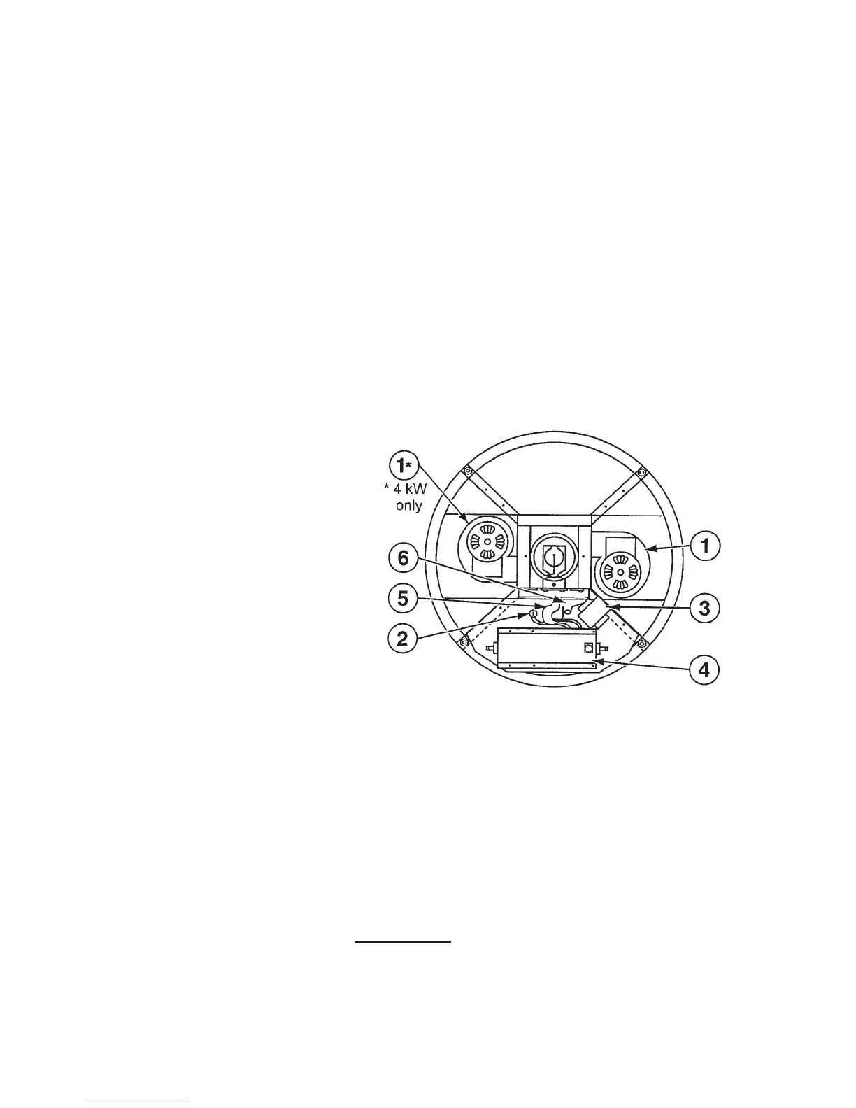
6.0 LAMPHOUSE ELECTRICAL COMPONENTS (2 & 4 kW Models)
1. Blower(s)
2. Spark Gap
3. Primary Transformer
4. R.F. Igniter Transformer
5. Doorknob Capacitor
6. R.F. Trap
LAMPHOUSE BASE PLATE
ELECTRICAL COMPONENTS
FIGURE 8
All high voltage igniter components,
cooling blower(s), thermal switch, and
DC power connectors to the xenon bulb
are located in the lamphead
(see Figures
8 & 9). The functions of the various com-
ponents are as follows:
6.1 IGNITER SYSTEM
The complete high voltage igniter circuit-
ry is located on the lamphead base plate.
To gain access to the internal electrical
components, it is only necessary to un-
latch the two draw-down latches located
at the bottom of the housing. Then, slide
theberglasshousingupwardandaway
from the tubular frame assembly. With
the components exposed, the individual
items that make up the igniter system
can be accessed.
DANGER
Before opening the lamphouse, disconnect all input power to the SkyTracker
so that the igniter cannot be accidentally operated. Severe electrical shock
can result if the igniter is accidentally operated when these parts are exposed.
16