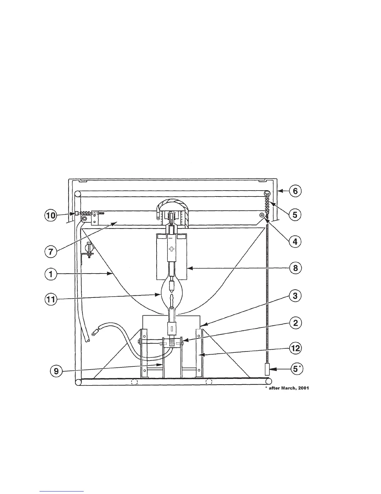
6.4 THERMAL SWITCH
Each lamphead is equipped with a Thermal Switch that will detect “High Temperature”
conditions. The switch is located on the upper bulb support spider (see Figure 9, Item 7).
When the temperature in a lamphead reaches a level that may be harmful to the system,
the Thermal Switch will open – turning that particular lamp off.
6.5 XENON BULB (LIGHT SOURCE)
The light source is supplied through the use of a high quality xenon bulb (see Figure 9).
The bulb is securely attached to the circuit to minimize mechanical and thermal stresses.
Instructions to install and remove the bulb are detailed in sections 8.0 and 9.0.
7.0 LAMPHEAD MECHANICAL COMPONENTS
FIGURE 9
1.ReectorAssembly 7.AnodeSupportSpider
2. Cathode Pin Receiver 8. Anode Adapter
3. Air Plenum 9. Lower Lamp Support
4. Thermal Switch 10. Bulb Centering Adjustment “X” and “Y”
5. Bulb Focus Adjustment “Z” 11. Xenon Bulb
6. Housing Assembly 12. Insulator Cover Plate (removed for clarity)
18