Page 21
6701 OPERATOR • REV2
Figure 2-18. Head Section Adjustment
b. By loosening two locking knobs beneath the
back section, an additional 1.5" of longitudinal
adjustment can be achieved. If desired, the
head section may be removed by loosening the
locking knobs and pulling it straight out of the back
section.
The 6701 Hercules Table has the capability of
attaching the head section to the leg section for
use as a foot extension ONLY. Do Not reverse the
patient on the table without first consulting with
SKYTRON.
Two locking knobs are located on the inside of the
leg section for securing the head section. See
figure 2-19.
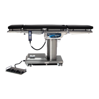
Figure 2-17. Emergency Brake Release
NOTE
•The Emergency Brake Release
Valve must be closed and tightened
(counter-clockwise) before activating
any hydraulic function.
•If the Emergency Brake Release
Valve has been operated, the BRAKE
UNLOCK button on the pendant control
will have to be pressed before brakes
will lock again.
2-9. Head Section
a. A quick release positioning bar located under
and to the front of the head section (figure 2-18)
is used to raise or lower the head section. Pull
the release bar toward the head end to allow the
section to pivot up or down. Positioning from 60°
above horizontal to 90° below horizontal in 15°
increments is available. Release the bar to lock
the head section in position.
SERVICE ACCESS
COVER
POWER
CORD
EMERGENCY
BRAKE RELEASE
BRAKE (4)
•Prior to unlocking brakes, check for
obstructions on the floor that might
prevent the table from moving smoothly
to new location. Relock the brakes
immediately once the final position
is reached and before commencing
surgery. Table brakes should remain
locked at all times if patient weight
exceeds 500 pounds.
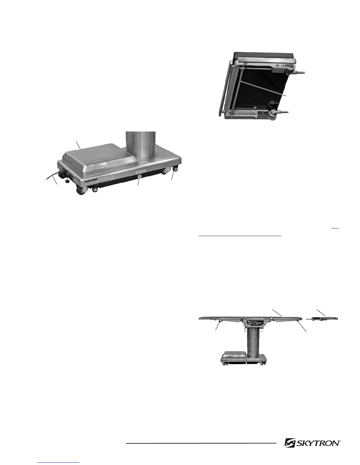
Figure 2-19. Repositioning Head Section
(for use as a Foot Extension)
HEAD
SECTION
FOOT/LEG
SECTION
LOCKING
KNOB
LOCKING
KNOB
 Loading...


