IF302 - Operation and Maintenance Instruction Manual
1.2
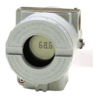
COVER
LOCKING
SCREW
Figure 1.1 - Cover Locking
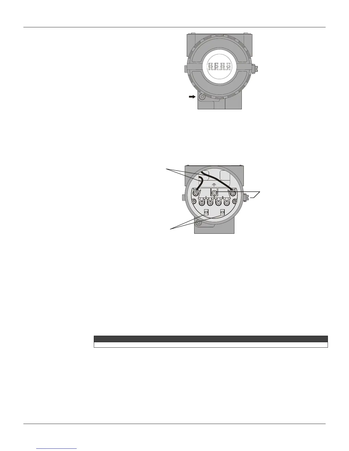
For convenience there are three ground terminals: one inside the cover and two externals, located
close to the conduit entries.
The wiring block has screws, on which fork or ring type terminals can be fastened, see Figure 1.2 -
Terminal Block.
GROUND
TERMINA
POWE
SUPPLY
TERMINALS
COMUNICATION
TERMINALS
Figure 1.2 - Terminal Block
The IF302 uses the 31.25 kbit/s voltage mode option for the physical signaling. All other devices on
the same bus must use the same signaling. 12 to 16 devices can be connected in parallel along the
same pair of wires.
Various types of Fieldbus devices may be connected on the same bus.
The IF302 is powered via the bus. The limit for such devices is 16 for one bus (one segment) for
non-intrinsically safe requirement.
In hazardous area, the number of devices may be limited by intrinsically safe restrictions.
The IF302 is protected against reverse polarity, and can withstand ±35 VDC without damage.
NOTE
Please refer to the General Installation, Operation and Maintenance Manual for more details.