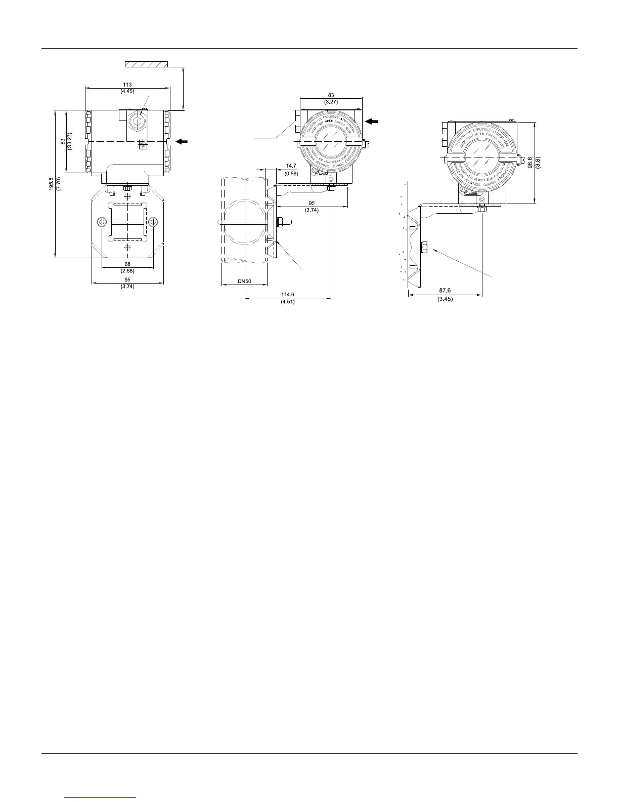
Installation
1.3
ALLOW 150 MM MINIMUM FOR LOCAL
ZERO AND SPAN ADJUSTMENT WITH
MAGNETIC TOOL.
COMMUNICATIONS
TERMINAL
PLUG
CONDUIT
CONNECTION
MOUNTING
BRACKET
PIPE 2"
PLUG
WALL OR
PANEL MOUNTING
FOR WALL MOUNTING
2 EXPANSION ANCHOR -
2 HEXAGON SCREW -
S8
3/16”X70
2 BOLT AND NUTS - 1/4”X30
NOT INCLUDED
FOR PANEL MOUNTING
Figure 1.3 - Dimensional Drawing and Mounting Positions
Topology and Network Configuration
Bus topology (See Figure 1.4 - Bus Topology) and tree topology (See Figure 1.5 - Tree Topology
Configuration) are supported. Both types have a trunk cable with two terminations. The devices are
connected to the trunk via spurs. The spurs may be integrated in the device giving zero spur length.
A spur may connect more than one device, depending on the length. Active couplers may be used
to extend spur length.
Active repeaters may be used to extend the trunk length.
The total cable length, including spurs, between any two devices in the Fieldbus should not exceed
1900m.