Installation
1.5
Input Wiring
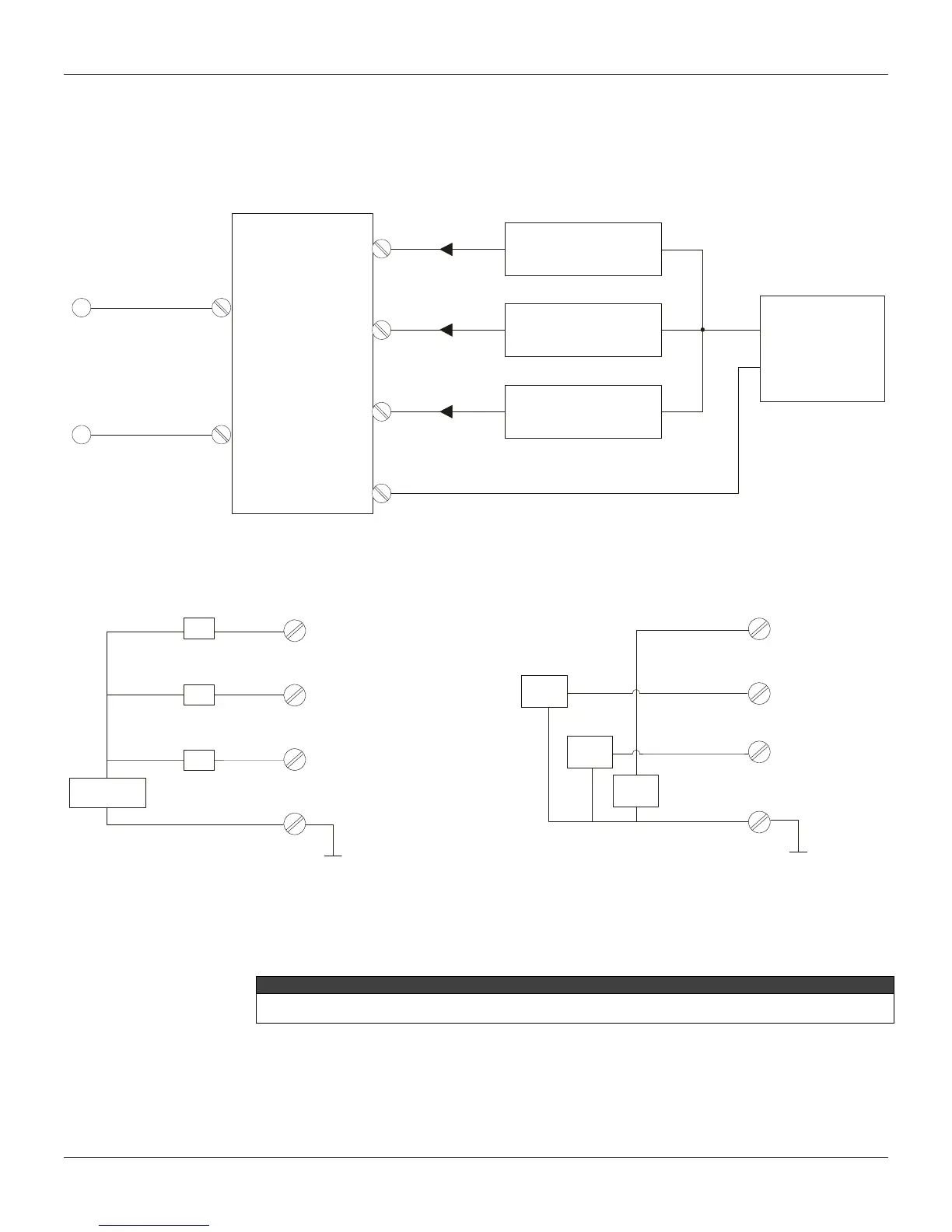
The IF302 accepts up to three current inputs in the range 0-20 mA or 4-20 mA. The three inputs
have a common ground and they are protected from reverse polarity signal. The inputs should be
connected as per Figure 1.6 - Input Wiring.
IF
FIELDBUS
4 a 20mA
TRANSMITTER 1
TRANSMITTER 2
TRANSMITTER 3
POWER
SUPPLY
+
_
+
+
+
+
_
1
2
3
4
Figure 1.6 - Input Wiring
Note that IF302 can operate with 0-20 mA or 4-20mA transmitters (See Figure 1.7 - Connection).
CHANNEL1
11
22
+
3
3
44
CHANNEL 2
4-20mA
CHANNEL 3
COMMON
NNE
TI
N
+
Power
Supply
-
TR
TR
-
+
-
+
TR
-
+
TR = Transmitter
-
-
+
-
0-20mA
0-20mA
0-20mA
+
4-wire 0-20mA Transmitters or
0-20mA Current Generator
CHANNEL1
CHANNEL 2
CHANNEL
COMMON
Figure 1.7 - Connection
Avoid routing input wiring close to power cables or switching equipment.
WARNING
Apply in the inputs of the conversor only current levels. Don't apply tension levels, because the shunt resistors
are of 100R 1W and tension above 10 Vdc it can damage them.