IF302 – Operation and Maintenance Instruction Manual
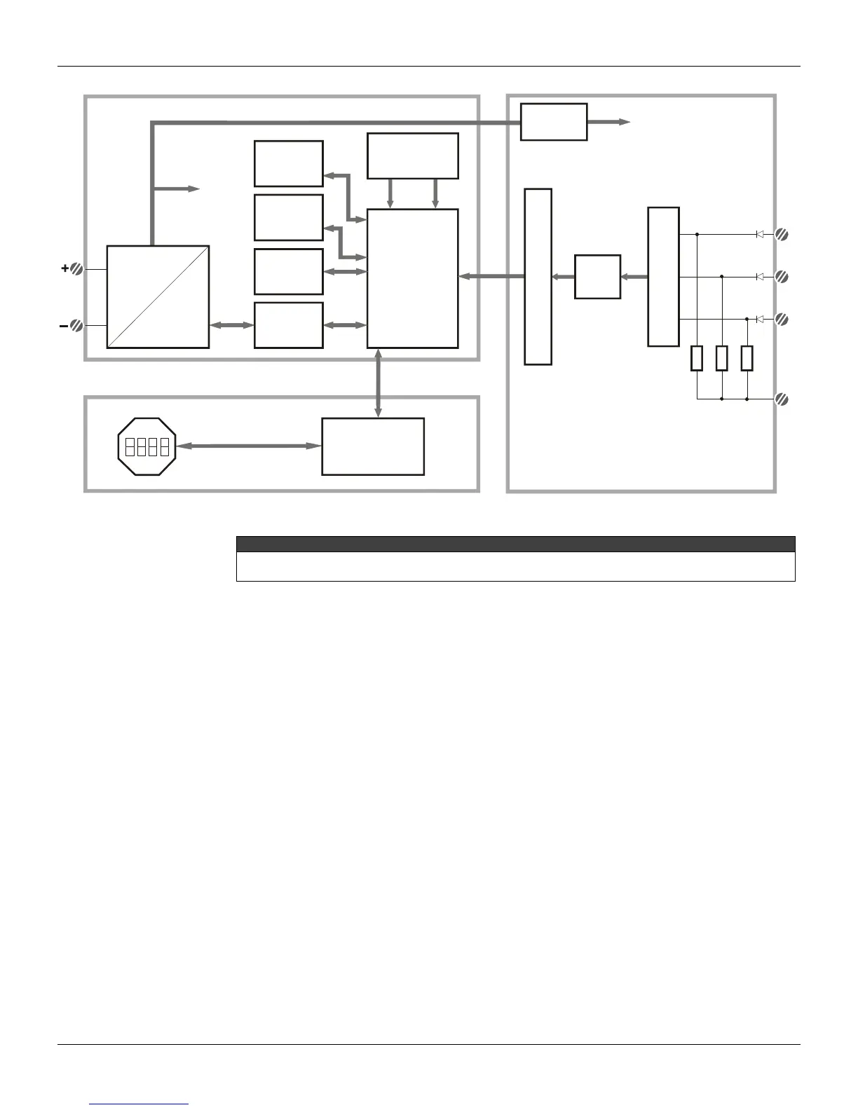
2.2
SUPPLY
FLASH
FIRMWARE
DOWLOAD
INTERFACE
RAM
MODEM
CPU
EEPROM
LOCAL ADJUST
POWER
ISOLATION
S
I
G
N
A
L
I
S
O
L
A
T
I
O
N
M
U
X
A/D
1
2
3
(*) Resistor Shunt
3 x 100
MAIN CIRCUIT BOARD INPUT CIRCUIT BOARD
DISPLAY BOARD
POWER
SUPPLY
DISPLAY
CONTROLLER
SIGNAL
SHAPING
Figure 2.1 - IF302 Block Diagram
* WARNING
Apply in the inputs of the conversor only current levels. Don't apply tension levels, because the shunt
resistors are of 100R 1W and tension above 10 Vdc it can damage them.