I
NSTALLATION
2-4
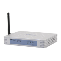
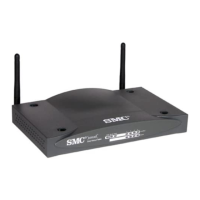
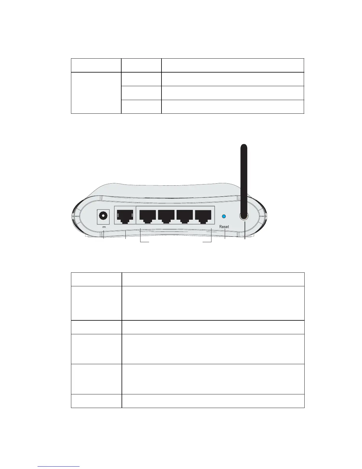
The following figure and table shows the rear panel of the Barricade.
Figure 2-2. Rear Panel
LAN 1~4 On Ethernet link.
Flashing The LAN port is sending or receiving data.
Off No Ethernet link.
Item Description
Power Inlet Connect the included power adapter to this inlet.
Warning: Using the wrong type of power adapter may cause
damage.
WAN Port WAN port (RJ-45). Connect your WAN line to this port.
LAN Ports Fast Ethernet ports (RJ-45). Connect devices on your local
area network to these ports (i.e., a PC, hub, switch or IP set
top box).
Reset Button Use this button to reset the power and restore the default
factory settings. To reset without losing configuration settings,
see “Reset” on page 4-60.
Antenna Fixed antenna is connected here.
LED Status Description
9V 1A WAN LAN4 LAN3 LAN2 LAN1
Reset
Button
Power
Connector
RJ-45 LAN Ports
RJ-45
Port
Antenna
 Loading...