D-*S-TFQ39
Page 3 of 3
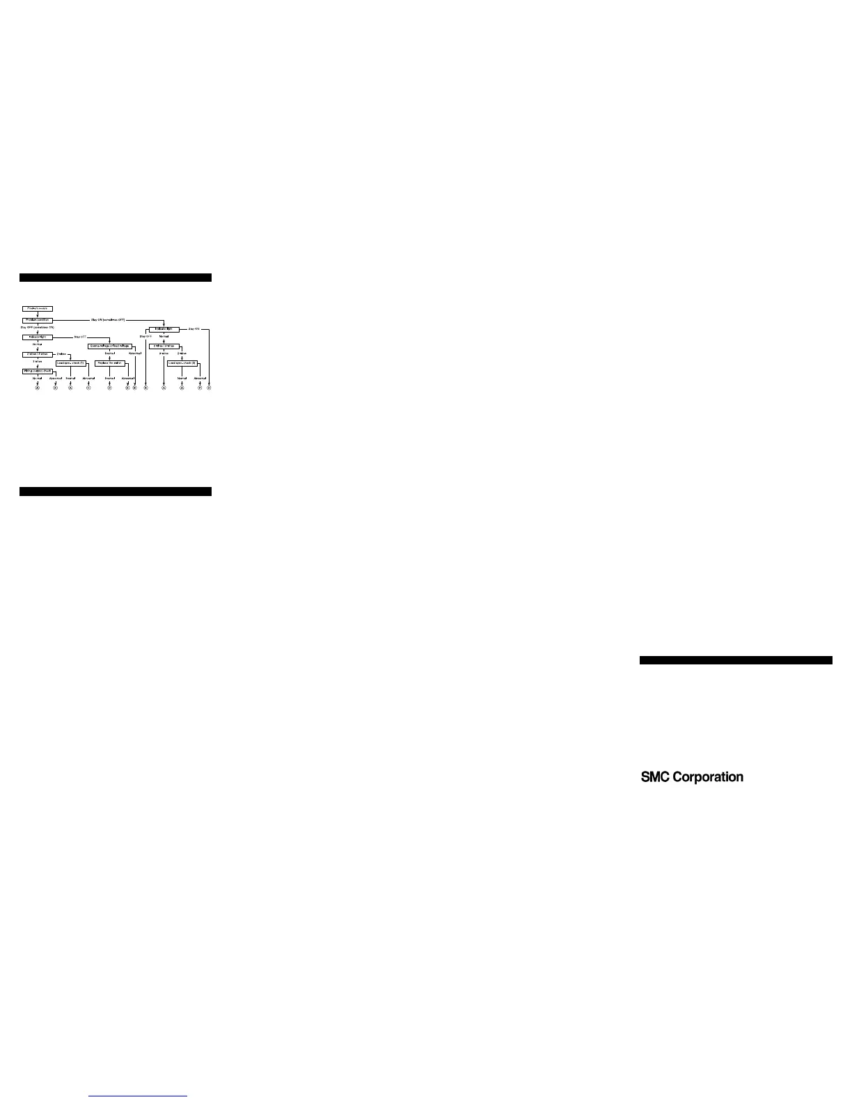
Troubleshooting
When detection failure occurs (stay ON/OFF), please follow the flow chart
below.
A: Switch output parts failure (replace)
B: Check wiring and correct fault
C: Replace switch 2 wires --> 3 wires
D: Switch failure
E: Replace cylinder. Detectable magnet field inadequate (No magnet)
F: Replace PLC input board or replace switch 2 wires --> 3 wires
Load specification checks
1) On voltage > Load voltage – Internal voltage drop
2) Off current > Leak current
Limitations of use
Any use in an EN ISO 13849 system must be within the specified limits and
application condition. The user is responsible for the specification, design,
implementation, validation and maintenance of the safety system
(SRP/CS)
Contacts
SMC Corporation,
Akihabara UDX15F, 4-14-1, Sotokanda, Chiyoda-ku, Tokyo 101-0021 JAPAN
Specifications are subject to change without prior notice from the manufacturer.
© 2013 SMC Corporation All Rights Reserved.
 Loading...