D-*S-TFQ39
Page 2 of 3
Operating Environment
Caution
(1) Do not use in a location where surges are generated.
When there are units (solenoid lifter, high frequency induction furnace, motor, etc.)
which generate a large amount of surge in the area around the actuator with solid
state auto switches, this may cause damage to the auto switch internal circuit.
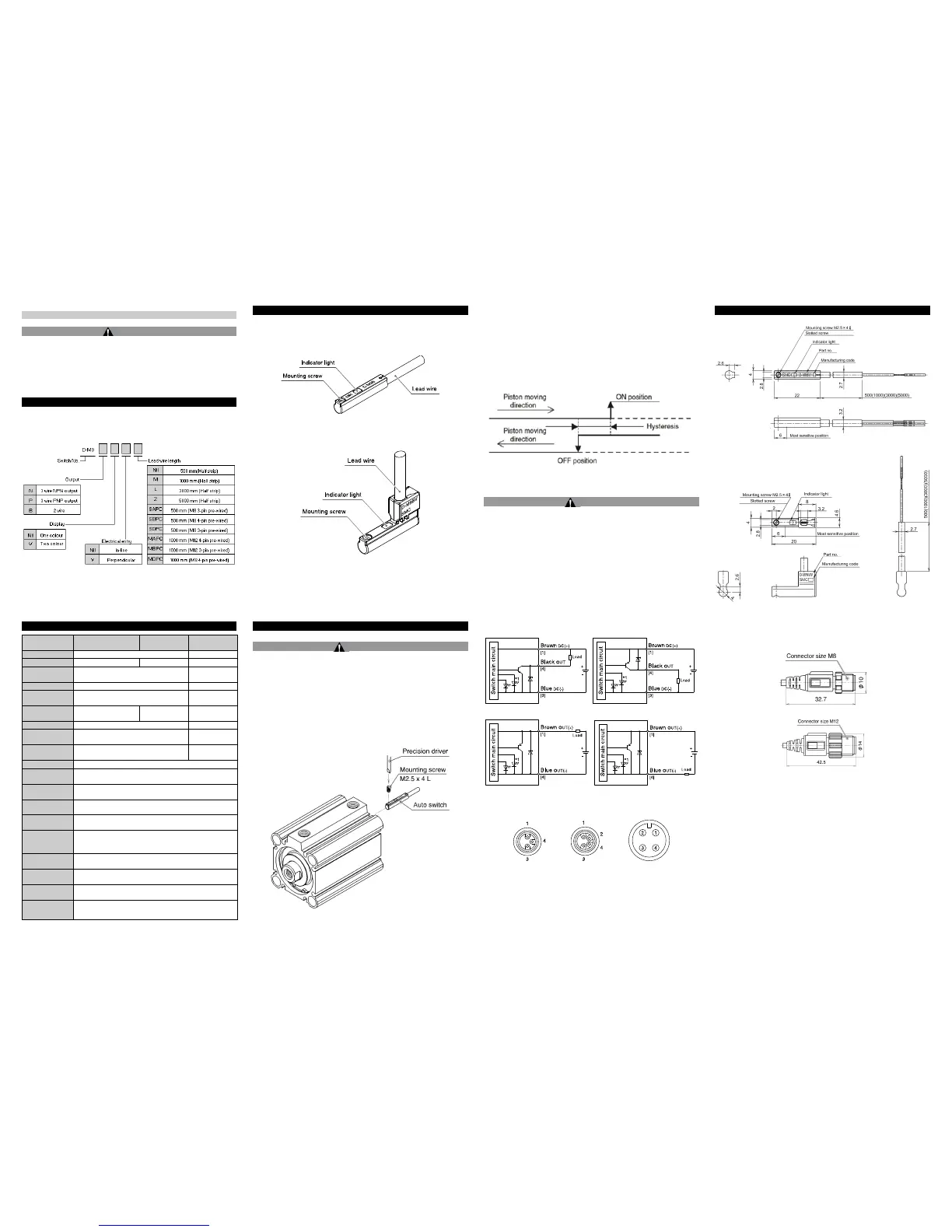
Model Indication and How to Order
Specifications
Oil-proof heavy-duty vinyl cord 2.7 x 3.2 oval, 0.15
mm2, 2 wire (D-M9B), 3 wire (D-M9N/D-M9P)
10 to 150 Hz, at the smaller amplitude,
1.5 mm or 20 m/s2 in X,Y,Z directions for 2 hours each
(De-energized)
Product Elements
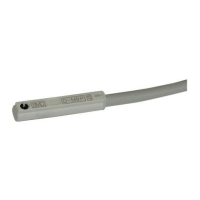
D-M9
D-M9V
Installation
Warning
• Do not install the product unless the safety instructions have been read
and understood.
Mounting
Each actuator has a specified mounting bracket for mounting the auto
switch.
"How to mount / Mounting bracket" depends on the actuator type and the
tube I.D. Please refer to the actuator catalogue.
When an auto switch is mounted for the first time, ensure that the actuator
is a type including a built in magnet, and select a bracket corresponding to
the actuator.
• Setting the detecting position
1) Set the actuator at the end of stroke.
2) Mount the auto switch in the position where the red LED is ON
(detecting position for the actuator end of stroke).
3) Based on the A and B dimensions in the actuator catalogue, set the
switch.
• Hysteresis
Environment
Warning
• Do not use in an environment where corrosive gases, chemicals, salt
water or steam are present.
• Do not install in a location subject to vibration or impact. Check the
product specifications.
D-M9N D-M9P
D-M9B (Sink input mode) D-M9B (Source input mode)
*1: For the D-M9(V) single colour auto switch the green LED is removed.
The number shown in brackets [ ] indicates the connector pin number.
M8 3-pin connector M8 4-pin connector M12 4-pin connector
Outline Dimensions (mm)
D-M9
D-M9V
External dimensions of Pre-wired connector
D-M9
A
,
B
PC
D-M9 DPC
 Loading...