URL http://www.smcworld.com (Global) http://www.smceu.com (Europe)
Specifications are subject to change without prior notice from the manufacturer.
© 2013 SMC Corporation All Rights Reserved
12 Contacts
AUSTRIA (43) 2262 62280-0
NETHERLANDS
(31) 20 531 8888
BELGIUM (32) 3 355 1464
NORWAY
(47) 67 12 90 20
CZECH REP. (420) 541 424 611
POLAND
(48) 22 211 9600
DENMARK (45) 7025 2900
PORTUGAL
(351) 21 471 1880
FINLAND (358) 207 513513
SLOVAKIA
(421) 2 444 56725
FRANCE (33) 1 6476 1000
SLOVENIA
(386) 73 885 412
GERMANY (49) 6103 4020
SPAIN
(34) 945 184 100
GREECE (30) 210 271 7265
SWEDEN (46) 8 603 1200 HUNGARY (36) 23 511 390
SWITZERLAND (41) 52 396 3131 IRELAND (353) 1 403 9000
UNITED KINGDOM
(44) 1908 563888
ITALY (39) 02 92711
BULGARIA (359) 2 974 4492
ESTONIA (372) 651 0370
ROMANIA
(40) 21 320 5111
LATVIA
(371) 781 77 00
LITHUANIA
(370) 5 264 8126
E
X600-TFR01
This product has no switches for setting, therefore the display cover
should not be opened.
5 Setting
•Parameter Setting
•Hardware Configuration
•I/O Map
•Diagnostic
10 Troubleshooting
Refer to the LED Display. Refer to the operation manual on the SMC
website (URL http://www.smcworld.com).
7 Outline Dimensions (mm)
Refer to the operation manual on the SMC website
(URL http://www.smcworld.com).
Refer to the operation manual on the SMC website
(URL http://www.smcworld.com
).
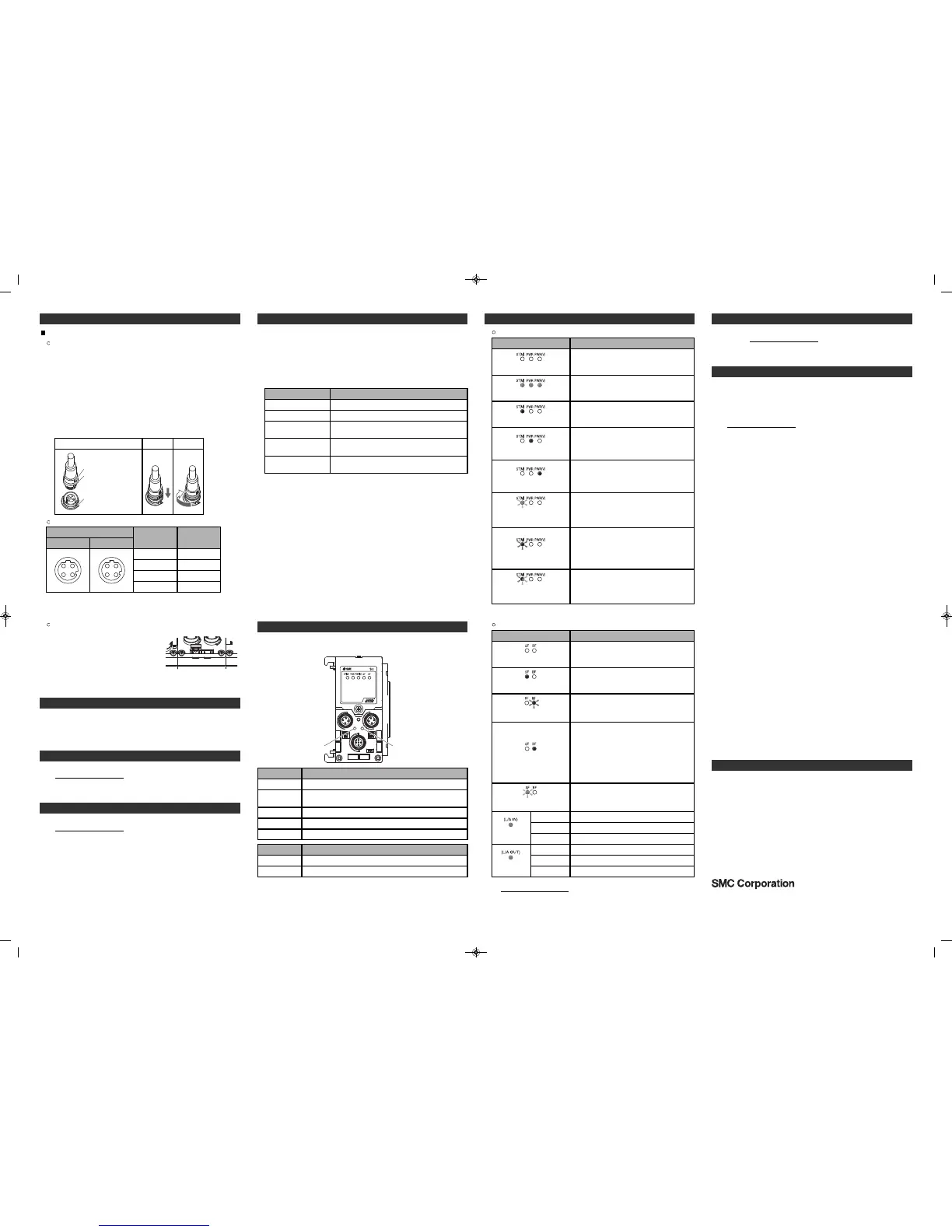
Display
ST(M)
PWR
PWR(V)
SF
Content
Displays the diagnostic status of the unit.
Displays the status of the power supply voltage for control
and input.
Displays the status of the power supply voltage for outputs.
Displays the system status.
BF Displays the communication status.
PROFINET status
Content
The communication with the PLC has been
established normally, or the power supply
for control and input is OFF.
LED display
OFF.
The communication with the PLC has been
established, but a diagnostic error has
occurred.
The SI unit received a Node flashing test
command.
Display
L/A IN
L/A OUT
Content
Displays the communication status of the BUS IN side.
Displays the communication status of the BUS OUT side.
Red SF LED is ON.
The configuration data of the PLC and
EX600 are not consistent.
Either of the following conditions:
•Power supply for the PLC is OFF.
•The cable between the PLC and SI unit is
not connected.
•The PLC or the SI unit is faulty.
•The configuration data of the PLC and the
Device Name of the SI unit are not
consistent.
BUS OUT side: No Link, No Activity
(Green)
BUS OUT side: Link, No Activity
BUS OUT side: Link, Activity
OFF
ON
Flashing
BUS IN side : No Link, No Activity
(Green)
BUS IN side : Link, No Activity
BUS IN side : Link, Activity
OFF
ON
Flashing
9 LED Display
The status display LED displays the power supply and communication
status.
SI unit common status
Content
The power supply for control and input is
OFF.
LED display
OFF.
The unit is in normal operation.
Green LEDs are ON.
An internal memory error has occurred in
the SI unit.
Red ST(M) LED is ON.
The power supply voltage for control and
input is abnormal.
(Control and input power supply voltage
monitoring parameter is valid)
Red PWR LED is ON.
The power supply voltage for outputs is
abnormal.
(Output power supply voltage monitoring
parameter is valid)
Red PWR(V) LED is ON.
A unit other than the SI unit has been
detected.
Green ST(M) LED is
flashing.
Either of the following conditions:
•The valve ON/OFF counter has exceeded
the set value.
•The valve is short circuited or
disconnected.
Red ST(M) LED is flashing.
Connection error between units has
occurred.
Red/Green ST(M) LED is
flashing alternately.
Refer to the operation manual on the SMC website
(URL http://www.smcworld.com).
Red BF LED is flashing.
Red BF LED is ON.
Green SF LED is flashing.
8 Maintenance
Turn OFF the power supply, stop the supplied air, exhaust the residual
pressure and verify the release of air before performing maintenance.
9 LED Display (continued)
6 How to order
Refer to the operation manual on the SMC website
(URL http://www.smcworld.com).
4 Installation (continued)
Connector pin assignment
TD+
Signal name
RD+
TD
-
1
Pin number
2
(2)
(3)
W
iring
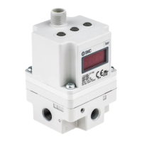
Connect the M12 connector cable.
The M12 SPEEDCON connector connection method is explained
below.
(1)Align mark B on the metal bracket of the cable connector
(plug/socket) with mark A.
(2)Align with mark C on the unit and insert the connector vertically.
If they are not aligned, the connector cannot be connected
correctly.
(3)When mark B has been turned 180 degrees (1/2 turn), wiring is
complete. Confirm that the connection is not loose. If turned too
far, it will become hard to remove the connector.
Mounting the marker
The signal name of the input or output
devices and unit address can be written
to the marker, and can be installed to
each unit.
Mount the marker (EX600
-
ZT1) into the
marker groove as required.
3
11 Commissioning
Cleaning method
Use a soft cloth to remove stains.
For heavy stains, use a cloth soaked with diluted neutral detergent and
fully squeezed, then wipe up the stains again with a dry cloth.
Do not use solvents such as benzene, thinner etc. to clean each unit.
Inspection item
Connector/wiring
Seal cap
Screws for mounting
and installation
Connection cables
Content of inspection
If the connector is loose, tighten it correctly.
If the seal cap is loose, tighten it correctly.
If the screws are loose, tighten according to the
specified torque.
If the cable is damaged or has any visual
abnormality, replace the cable.
Supply voltage
Check that the supply voltage is within
specification (24 VDC ±10%).
How to reset the product for power cut or forcible de-energizing
Supply power to the product.
The output status from just before the power was disconnected will not be
maintained when the power supply is recovered.
Start operation of the product after confirming the safety of the entire
system.
 Loading...