

M
Mrs. Amber PaceAug 7, 2025
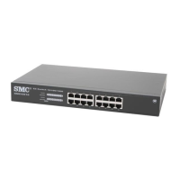
Why is the indicator LED on my SMC Networks ISE30A Switch operating incorrectly?
- EegomezAug 7, 2025
If the indicator LED on your SMC Networks Switch operates incorrectly, this suggests the product is faulty.
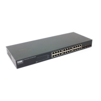
Why is the indicator LED on my SMC Networks ISE30A Switch operating incorrectly?
If the indicator LED on your SMC Networks Switch operates incorrectly, this suggests the product is faulty.
Why is the Indicator LED ON on my SMC Networks Switch?
If the indicator LED is ON, it indicates that the product is faulty.
Why is the Indicator LED OFF on my SMC Networks ISE30A?
If the indicator LED is OFF, this suggests the product is faulty.
Definitions of hazard levels (Caution, Warning, Danger).
Responsibility for compatibility and need for trained personnel.
Precautions before servicing and conditions requiring consultation.
Warranty terms, disclaimers, and legal compliance.
Prohibition of use as instruments for legal metrology.
Target audience, manual reading, and general safety warnings.
Warnings on disassembly, operation conditions, hazardous atmospheres, static electricity.
Safety instructions for performing maintenance.
Touching terminals, post-maintenance, design/handling notes.
UL approval, voltage, load, air quality, fluid compatibility.
Guidelines for installation and mounting.
Correct wiring, noise prevention, insulation.
Avoiding unsuitable environments.
Avoiding chemicals, surges, vibration, temperature cycles, sunlight, heat.
Power-on, load handling, button usage, warm-up.
Safety steps, regular checks, drainage, cleaning.
Guide to specifying product model numbers.
Overview of available options.
List of accessories and their part numbers.
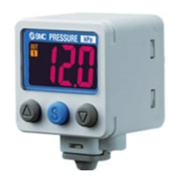
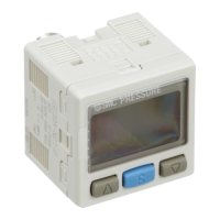
Labels for physical components.
Functions of LEDs, LCD, and buttons.
Indication of the selected unit.
2-colour, 7-segment, analogue output, auto preset.
Bottom value, chattering, copy function, digit, error indication, fine adjustment.
F.S., function selection mode, hysteresis.
Indication accuracy, color, Indicator LED, Key lock.
Load impedance, measurement mode, normal output, NPN/PNP, operating mode, output impedance, output type, peak value, piping-port size.
Power saving, pressure setting, response time, reversed output.
Rated pressure range, R.D., repeatability, units selection.
Ripple, wetted part, window comparator mode, withstand voltage, zero clear.
Instructions for mounting using brackets A and B.
Mounting details for Bracket C.
Instructions for mounting using a panel mount adapter.
Procedure for safely removing the switch.
Steps for connecting tubing with a one-touch fitting.
Warning and tube diameter tolerance.
Guidelines and noise prevention.
Procedures for connector and pin assignments.
Circuits for NPN outputs.
Circuits for PNP outputs.
Circuits for analogue outputs.
Primary operating mode and ON/OFF logic.
Steps for setting pressure in hysteresis mode.
Using buttons to change set values.
Completing settings and resetting display to zero.
Accessing settings and default configurations.
Changing the pressure display unit.
Configuring the first output.
Configuring the second output.
List of other configurable functions.
Step-by-step guide for unit selection.
Setting output mode, reversed output, and pressure for OUT1.
Adjusting the hysteresis for OUT1.
Choosing the display colour for OUT1.
Setting the output method for OUT2.
Selecting response time to prevent chattering.
Changing display resolution to prevent flickering.
Automatic pressure value calculation.
Step-by-step guide for setting auto-preset for OUT1 and OUT2.
Manual fine adjustment of the displayed pressure.
Mode to reduce power consumption.
Selecting a security code to lock/unlock keys.
Explains hysteresis and window comparator modes for normal output.
Explains hysteresis and window comparator modes for reversed output.
Setting all functions sequentially.
Table of function order and applicability.
Connecting switches and enabling the copy function.
Indicating copy readiness and completion.
Procedure for checking the first output.
Procedure for checking the second output.
Restoring product to default configurations.
Displaying max/min pressure and adjusting display to zero.
Locking/unlocking keys without a security code.
Locking/unlocking keys using a security code.
Changing and entering the security code.
Resetting after power loss and replacing fittings.
Contacting SMC if the code is lost.
Diagnostic steps for operational problems.
Diagnostic steps for display issues.
Details on output, wiring, chattering, and response time issues.
Details on analogue output and system error faults.
Details on display fluctuations, missing parts, flashing, and pressure differences.
Details on accuracy, unit change, button operation, looseness, noise, and copy errors.
Details on copy function failure and unstable operation.
Er1/Er2, Er3, and pressurizing errors.
Er0, Er4, Er6-Er9 for internal data errors.
Model numbers, pressure ranges, voltage, current.
Repeatability, hysteresis, analogue outputs.
Accuracy, LEDs, operating conditions, standards.
Details on port sizes, fittings, and materials.
Product weight and output graphs.
Overall physical dimensions.
Dimensions for different piping configurations.
Dimensions for mounting brackets A and B.
Dimensions for bracket C and panel adapter.
Required panel cut-out sizes for a single switch.
Panel cut-outs for horizontal and vertical arrangements.
Record of changes and updates to the manual.
| Brand | SMC Networks |
|---|---|
| Model | ISE30A Series |
| Category | Switch |
| Language | English |