C
HAPTER
1
| Introduction
Overview
– 27 –
POWER SUPPLY INLET
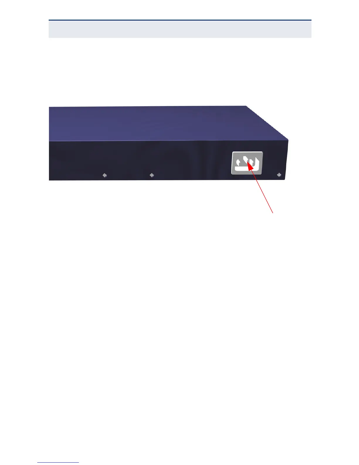
There is one power inlet on the rear panel of the switch. The standard power
inlet is for the AC power cord.
Figure 4: Power Supply Inlet
GROUNDING POINT
To prevent accidental electrical shock or damage to your switch, it is
recommended that you ground the switch to an earth point by attaching a
grounding wire (not supplied) to the grounding point located on the rear panel,
with a metal screw. If located in a tall building, grounding points include metal
drain pipes, and other electrostatic conductive devices that lead to the ground,
or if located on the first floor of a building, the ground outside itself.
AC 100-240Vac, 50~60Hz, 1.7AAC 100-240Vac, 50~60Hz, 1.7A
 Loading...