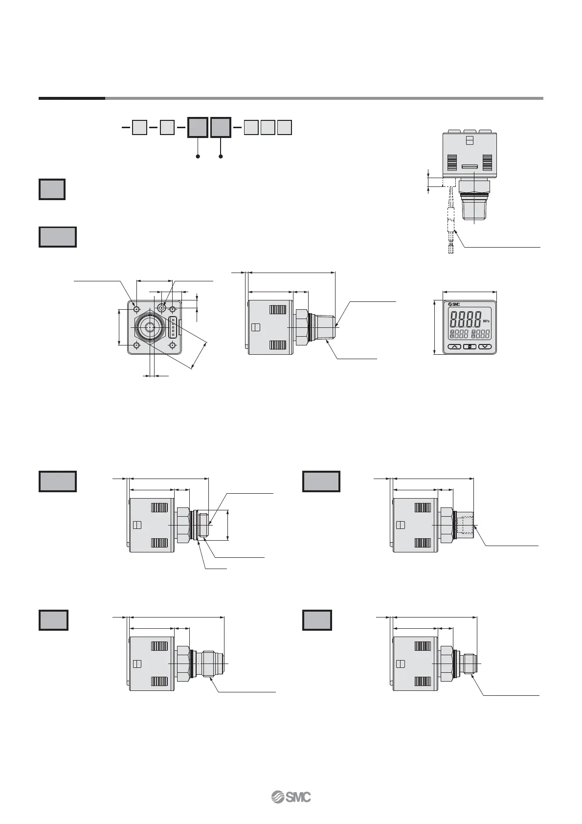
30
30
25 8.5
02: 48.4
N02: 48.9
M5 x 0.8
Thread depth 5
Piping port
02: R1/4
N02: NPT1/4
1.5
20
20
11
4 x Ø 2.6
Depth 7 or less
Atmospheric
vent port
4.2
17
2.5
5
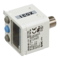
Lead wire with connector
25 8.5
441.5
Ø 17
M5 x 0.8
Thread depth 5
Piping port G1/4
Gasket
45
25 8.5
1.5
Piping port Rc1/8
52.7
25 8.5
1.5
Piping port URJ1/4
25 8.5
46.71.5
Piping port TSJ1/4
F02
C01
N02
02
A2
B2
Dimensions
Piping specifi cation Piping direction
R1/4
G1/4 Rc1/8
NPT1/4
URJ1/4 TSJ1/4
If there is a possibility that the atmospheric vent port of the switch will be exposed to water or dust, insert a tube into the
atmospheric vent port and route the other end of the tube to a safe place away from water or dust.
∗ For tubing, please use the SMC TU0425 (polyurethane, O.D. Ø 4, I.D. Ø 2.5) for the pressure switch.
∗ If it is expected that the pressure, such as water hammer or surge pressure, will fluctuate rapidly, refer to the
precautions in the Operation Manual on the SMC website (http://www.smc.eu).
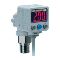
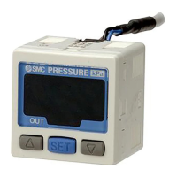
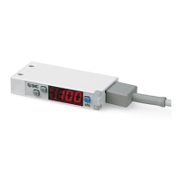
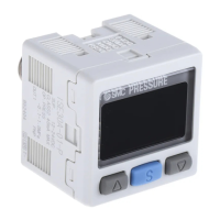
ZSE20C(F)
ISE20C(H)
23
ZSE20C
(
F
)
/ISE20C
(
H
)
Series
 Loading...