Installation
164
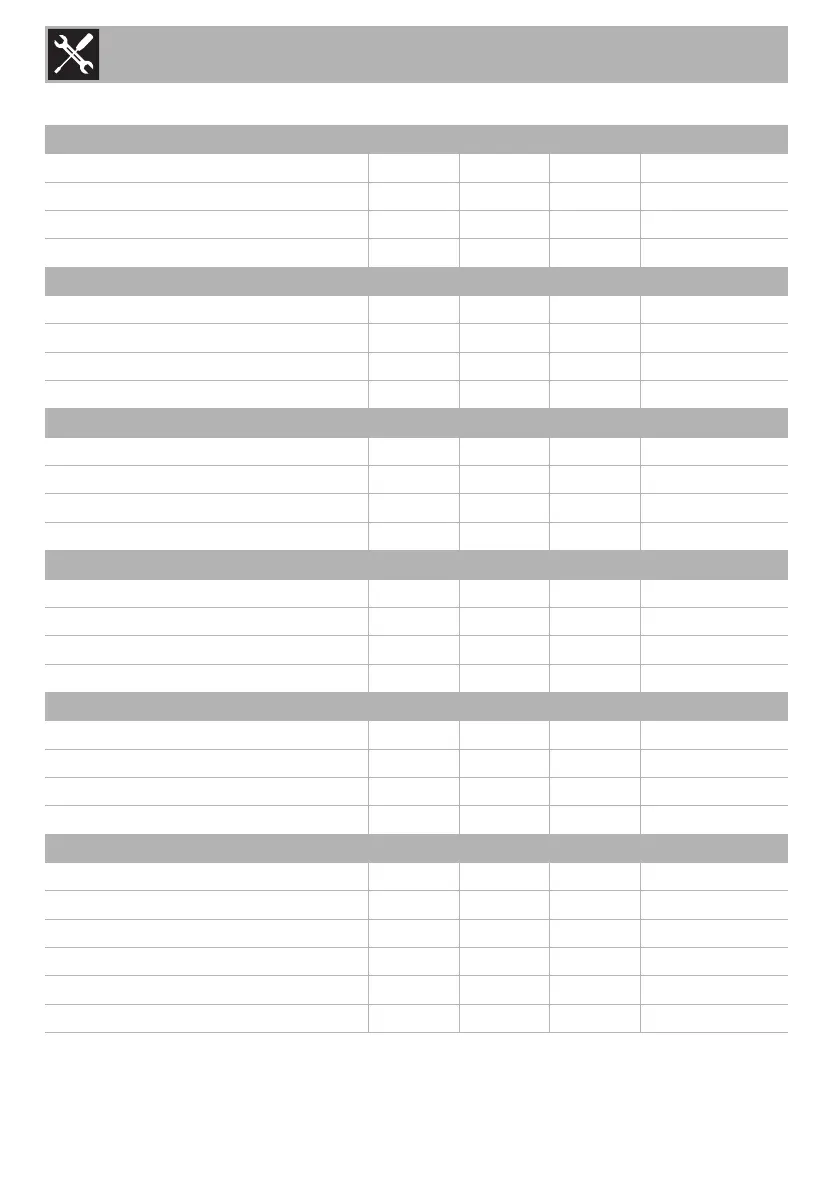
Burner and nozzle characteristics tables
1 NATURAL gas – G20 20 mbar AUX SR R UR2
Rated heating capacity (kW)
1.0 1.8 3.0 4.2
Nozzle diameter (1/100 mm)
72 97 120 145
Pre-chamber (printed on nozzle)
(X) (Z) (H9) (F3)
Reduced flow rate (W)
400 500 800 1200
2 Natural gas G20 – 25 mbar AUX SR R UR2
Rated heating capacity (kW)
1.1 1.8 2.9 4.1
Nozzle diameter (1/100 mm)
72 94 110 145
Pre-chamber (printed on nozzle)
(X) (Z) (H8) (H3)
Reduced flow rate (W)
400 500 800 1200
3 Natural gas G25.1 – 25 mbar AUX SR R UR2
Rated heating capacity (kW)
1.1 1.8 3.1 4.1
Nozzle diameter (1/100 mm)
77 100 134 152
Pre-chamber (printed on nozzle)
(F1) (Y) (F3) (F3)
Reduced flow rate (W)
400 500 800 1200
4 Natural gas G25 – 20 mbar AUX SR R UR2
Rated heating capacity (kW)
1.0 1.8 3.0 4.0
Nozzle diameter (1/100 mm)
77 100 134 165
Pre-chamber (printed on nozzle)
(F1) (Y) (F3) (H3)
Reduced flow rate (W)
400 500 800 1200
5 Natural gas G2.350 – 13 mbar AUX SR R UR2
Rated heating capacity (kW)
1.0 1.8 2.9 3.8
Nozzle diameter (1/100 mm)
94 120 165 190
Pre-chamber (printed on nozzle)
(Y) (Y) (F3) (F3)
Reduced flow rate (W)
400 500 800 1200
6 Liquid gas – G30/31 - 30/37 mbar AUX SR R UR2
Rated heating capacity (kW)
1.0 1.75 3.0 4.0
Nozzle diameter (1/100 mm)
50 65 85 100
Pre-chamber (printed on nozzle)
--- -
Reduced flow rate (W)
400 500 800 1300
Rated flow rate G30 (g/h)
73 127 218 291
Rated flow rate G31 (g/h)
71 125 214 286