39
Instructions for the installer
Make the connection to the gas mains using a rubber hose
whose specifications comply with current standards (verify that
the reference standard is stamped on the hose).
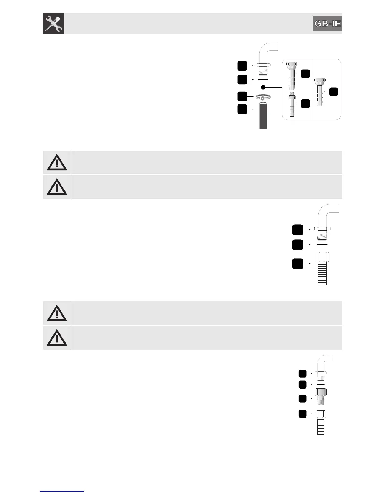
Carefully screw the hose connector 3 to the appliance’s gas
connector 1 (1/2” thread ISO 228-1), placing the seal 2
between them. The hose connector 4 can also be screwed to
the hose connector 3, depending on the diameter of the gas
pipe used. After having tightened the hose connector(s), push
the gas pipe 6 onto the hose connector and secure it with the
clamp 5 that is compliant with the applicable standard.
11.3.2Connection with a flexible steel hose
CAUTION: The following instructions are valid for all types of installation, see fig. A, B, C in
chapter “11.1 Installing in kitchen units”.
Only use standards-compliant continuous wall steel hoses no longer than 2 metres.
This type of installation can be used for both built-in and free-standing appliances.
Make the connection to the gas mains using a continuous wall flexible steel pipe
whose specifications comply with the applicable standard.
Carefully screw the connector 3 to the appliance’s gas connector 1 (1/2” thread ISO
228-1), placing the seal 2 between them.
11.3.3Connection with a flexible steel hose with conical fitting (where present)
CAUTION: The following instructions are valid for all types of installation, see fig. A, B, C in
chapter “11.1 Installing in kitchen units”.
Only use standards-compliant continuous wall steel hoses no longer than 2 metres.
This type of installation can be used for both built-in and free-standing appliances.
Make the connection to the gas mains using a continuous wall flexible steel pipe
whose specifications comply with the applicable standard.
Carefully screw the connector 3 to the appliance’s gas connector 1 (½” thread ISO
228-1), placing the seal 2 between them. Apply insulating material to the thread of
the connector 3, and then tighten the flexible steel pipe 4 to the connector 3.


 To Next Page