Do you have a question about the Smitec Cosmos Series and is the answer not in the manual?
Ensures proper understanding of the manual and safe operation of the equipment.
Details necessary precautions and tool usage for safe handling and assembly.
Highlights critical safety measures to prevent electric shock during installation and operation.
Advises caution regarding high temperatures of components during and after operation.
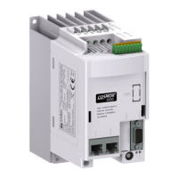
Provides an overview of the COSMOS-3000 series, its core components, and digital control logic.
Explains how to identify different COSMOS 3000 models based on power, field bus, and other features.
Lists standard driver configurations with order codes and type numbers for the first series.
Details the alpha-numeric code structure that defines specific features of each COSMOS 3000 driver.
Lists available connectors and accessories for COSMOS 3000 drivers, along with their order codes.
Provides detailed electrical ratings for COSMOS 315X, 325X, and 350X models, including power and output.
Illustrates thermal dissipation graphics for COSMOS 315X and 325X based on output current and switching frequencies.
Lists environmental and installation specifications for COSMOS 315X, 325X, and 350X, including temperature and humidity.
Explains EMC compliance standards and conditions for COSMOS 3000 drivers, including wiring requirements.
Provides the weight specifications for COSMOS 315X, 325X, and 350X models.
Shows dimensional drawings for COSMOS 315X and 325X models.
Presents dimensional drawings for the COSMOS 3500/1 (first series) servo drive.
Provides dimensional drawings for the COSMOS 3500/1 (second series) servo drive.
Shows dimensional drawings for the COSMOS Type 3502 servo drive.
Details optimal positioning and mounting methods for COSMOS 3000 drivers in electrical panels.
Offers a template and instructions for mounting COSMOS 315X/325X models.
Provides a template and instructions for mounting COSMOS 3500/1 (first series) models.
Provides a template and instructions for mounting COSMOS 3500/1 (second series) models.
Provides a template and instructions for mounting COSMOS Type 3502 models.
Guides on connecting power supplies and motor outputs for COSMOS 3000 drivers.
Details the connection of mains, auxiliary voltage, motor output, and DC BUS power.
Explains the connection of signal wiring, including encoder, STO, I/O, and field bus.
Emphasizes the importance of proper earth wiring for safety and device functionality.
Details the features of allowed cables and connectors for COSMOS 3000.
Describes the connection and specifications for the 24VDC auxiliary power supply input.
Provides connection details for the main power supply input (LINE/J1).
Explains the connection and specifications for the motor output (MOTOR/J4).
Details the connection and specifications for the DC BUS power supply (DC BUS/J3).
Describes the connection and specifications for the dynamic brake output (BRAKE R/J2).
Details the configuration and connection for Encoder 1 input (E1).
Shows encoder connection types (24V OC/HTL, Diff. 5V) for COSMOS 3XXX (first series).
Details encoder connection types (24V OC/HTL, Diff. 5V) for COSMOS 3XXX (second series).
Explains the function and connection for Encoder input/output 2 (E2).
Details the input signals for a second encoder type, primarily for Hyperface encoders.
Describes the output function for repeating encoder signals to acquisition devices.
Details the STO system I/O signals for integrated safety, ensuring motor power absence.
Explains the general purpose I/O connector for driver control and setup.
Covers field bus connections for driver communication with control systems.
Describes the FLxIO communication bus based on EIA-RS485 physical layer.
Explains Sercos III/Modbus TCP communication buses based on Ethernet 100Mbps.
Details Sercos II field bus connections using optical fiber for industrial machines.
Specifies the connection for the VISIO 3000 operator interface.
Describes the USB port usage for firmware updates and diagnostics.
Presents a schematic diagram illustrating the electrical connections for the COSMOS 3000 driver.
Provides guidelines for selecting appropriate wires and fuses for power supply and conductor protection.
Details cable sizing and fuse ratings according to IEC 61800-5-1 standards.
Summarizes recommended fuse characteristics for UL applications based on IEC/UL 61800-5-1 and C22.2 No.274.
Outlines installation requirements for UL certification, including short circuit and motor overload protection.
Details the STO function, its features, and safety integrity levels.
Describes the operational aspects of the safety integrated system and its signals.
Provides electrical specifications for STO inputs and related signals.
Shows possible statuses of the safety circuits, including enabling conditions.
Details the intervention times for safety inputs and STO function activation.
Explains the navigation and data modification functions of the VISIO 3000 interface keys.
Describes menu navigation and access levels for interacting with the driver via the LCD.
Explains how to interpret status messages displayed on the LCD, including driver and field bus status.
Details status display for Sercos III, FLxIO, Sercos II, Analogue, Service, and Modbus TCP controllers.
Explains how to change parameter access levels by entering passwords.
Shows the menu hierarchy, entries, minimum access level, and descriptions for the main menu.
Lists measured values and min/max recorded values for various motor types.
Provides access to driver status, last errors, and hardware diagnostics.
Covers controller settings and parameters for driver control systems.
Allows setting motor type and corresponding parameters for different motor types.
Explains Sercos standard features, interface configuration, and status for Sercos II versions.
Describes analogue controller configurations and I/O signals.
Provides parameters for motor control via VISIO when the controller is set to SERVICE mode.
Contains parameters for the external brake resistor, applicable when the dynamic brake output is present.
Covers digital I/O and analogue output settings for Sercos II versions.
Covers driver configuration parameters for various motor types and Sercos II.
Present in Sercos III models, this menu displays Ethernet connection parameters.
Available for asynchronous motors, this menu allows setting encoder parameters.
Configures VISIO 3000 operation options, including LCD lighting, display reset, and language.
Describes how to set the field bus address using rotary selectors and hexadecimal notation.
Indicates the status of the main power supply (LINE) and auxiliary power supply (24VDC) via LEDs.
Explains the driver's general status indicated by FLT (fault) and STS (status) LEDs.
Describes the meaning of I1, I2, and TO LEDs related to the STO safety system.
Explains the meaning of LEDs A and L for field bus connections (Ethernet IP/Sercos III).
Details the field bus status LEDs (FBS) for FLxIO and Sercos III.
Describes address setting for Sercos II using the Visio operator interface.
Indicates power availability, driver enabled status, and digital I/O status via LEDs.
Details the F, B, S LEDs for driver and Sercos error codes in Sercos II models.
Indicates a serious hardware error via the red Fault LED.
Indicates distortion or interruption of the Sercos II optical signal.
Details internal errors originating from control circuits or firmware, indicating critical problems.
Lists control errors from external problems or power section, requiring specific procedures for elimination.
Details control errors for brushless motors, including VRef limits, current, and temperature issues.
Lists control errors for asynchronous motors, covering auxiliary voltage, temperature, and ventilation issues.
Lists warning codes related to STO enabling and ventilation for different motor types.
Details driver error codes indicated by FBS LEDs for Sercos II, covering VRef limits, current, protection.
Lists Sercos error codes related to communication, phase transitions, and SERCON chip issues.
Provides guidance on diagnosing and resolving SERCOS communication problems.
Step-by-step guide for updating firmware using a PC, Windows XP or later, and Winmicro software.
Details the procedure for replacing the fan blower in COSMOS Type 315X/325X models.
Explains how to replace the dynamic brake resistor in COSMOS Type 325X.
| Brand | Smitec |
|---|---|
| Model | Cosmos Series |
| Category | Servo Drives |
| Language | English |