ASSEMBLY INSTRUCTIONS
ASSEMBLY STAGE
#3
Assembly Hardware Required:
#31
Button Head Allen Screw Qty. 2 #40 Flat Washer Qty.16
#32 Button Head Allen Screw Qty. 2 #41 Flat Washer Qty. 8
#33 Button Head Allen Screw Qty. 4 #42 Nylon Nut Qty. 8
#36 Button Head Allen Screw Qty. 4 #43 Nylon Nut Qty. 4
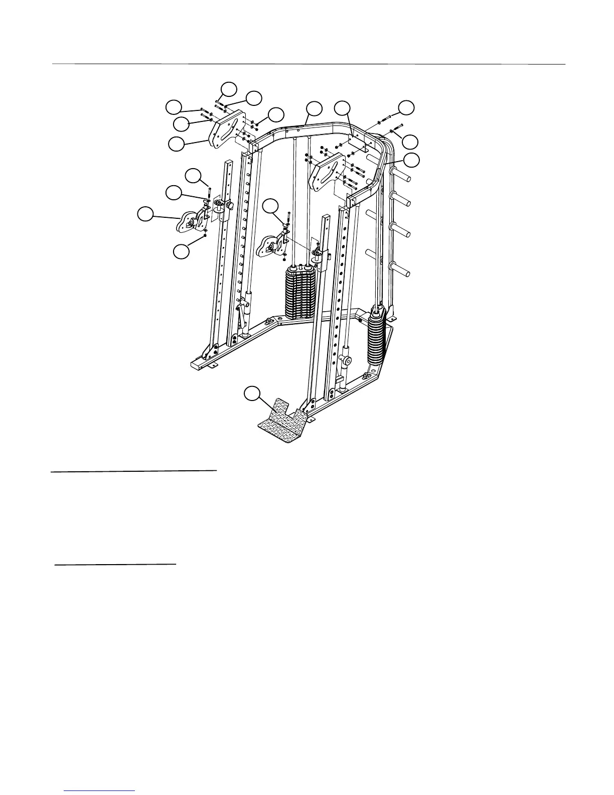
Assembly Description:
A) SECRULY assemble the Right Top Brace (#12) and the Left Top Brace (#13) to the Rear Base
(#3) using 1 – L Bracket (#19), 2 – Button Head Allen Screw (#32), 4 - Flat Washer (#40) and 2 -
Nylon
nut
(#42)
.
B) Tight the Linear Shaft (#22), the Guide Rod (#21) to the Top Brace with Set Screws on per side
as
shown
.
C) SECRULY assemble the 2 – Top Beam (#17) to the Top Brace and the Olympic Bar Support
using 2 – Button Head Allen Screw (#36), 4 – Flat Washer (#41), 2 – Nylon Nut (#43), 2 –
Button Head Allen Screw (#33), 4 – Flat Washer (#40) and 2 – Nylon Nut (#42) on per side as
shown.
D) Assemble the Swiveling Pulley Handles (#16) to the Left Handle Bar Adjustable (#8), the Right
Handle Bar Adjustable (#9) using 2 – Button Head Allen Screws (#31), 4 – Flat Washers (#40)
and 2 – Nylon Nuts (#42) as shown.
Page 9
17
36
41
43
33
40
31
40
16
42
12
13
19
32
40
72
65