I
2
S DSD CHANNEL
DSDL=PCM DATA (The DSD left channel using the PCM DATA pin)
DSDL=PCM LRCK (The DSD left channel using the PCM LRCK pin)
Note: When using the I
2
S input to streaming DSD audio, if you find that
the left and right channels are incorrect, you can use this option to
correct it.
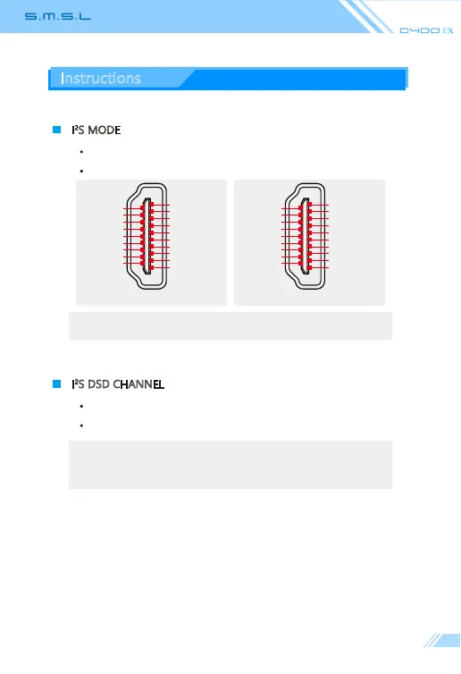
I
2
S MODE
NORMAL
REVERSED
Note: This option is used to match different I
2
S interface standards, please
check the interface definition of the signal source before use
Instructions
NORMAL
I
2
S D ATA +
I
2
S D ATA -
I
2
S LRCLK +
I
2
S LRCLK -
GND
NC
DSD FLAG
NC
GND
GND
GND
GND
I
2
S MCLK +
I
2
S MCLK -
NC
MUTE
NC
I
2
S BCK +
I
2
S BCK -
2
1
18
19
REVERSED
GND
GND
I
2
S MCLK +
I
2
S MCLK -
NC
MUTE
NC
I
2
S BCK +
I
2
S BCK -
I
2
S D ATA -
I
2
S D ATA +
I
2
S LRCLK -
I
2
S LRCLK +
GND
NC
DSD FLAG
NC
GND
GND
2
1
18
19