Page 8 Operation Manual
1.0 INTRODUCTION
Congratulations on your purchase of the EEWH31 1B
air-electric tire changer. This tire changer is designed
for ease of operation, safe handling of rims, reliability
and speed. This combination of features means more
prof t and added versatility for your shop, enabling you
to work with aluminum or magnesium alloy wheels with
reduced risk of damage. With a minimum of maintenance
and care your EEWH311B Air-Electric Tire Changer will
provide many years of trouble-free operation.
Please read this manual thoroughly before operating the
unit. Instructions on use, maintenance and operational
requirements of the machine are covered in this manual.
1.1 SPECIFICATIONS
Operation temperature range: +41/+122 F (+5/50 C)
Air-Electric tilt back tower tire changers for car , light
commercial vehicle and motorcycle tires designed for
one-piece rims. Dimensions based on OEM tires and
wheels only.
Air-Electric
Air pressure required 140-170 psi (8.5 cfm)
Electrical Requirements 115V 60Hz 1ph 20A
Bead breaker force 3300 lbs (kN 15)
Bead Breaker Positions 3
Bead Breaker position #1 3.5” to 13”
Bead Breaker position #2 4” to 14.5”
Bead Breaker position #3 4.5” to 15.5”
Turn Table Operation Single Speed with Reverse
Turn Table Torque (lb - ft) 738
Turn Table Speed (RPM) 7 CW / 7 CCW
Max. tire diameter 40” (mm 1016)
Max. tire width 15” (381mm)
Max. wheel width 15” (381mm)
Rim diameter outside locking 10”-24”(254-609mm)
Rim diameter inside locking 12”-24”(305-609mm)
Motor 1 Hp (kw .75)
Machine weight 750lbs (340kg)
Shipping Weight 838 lbs (380 kg)
Overall dimensions 69” x 41” x 55”
Warranty 2 years
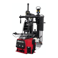
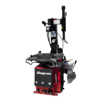
1.2 NOMENCLATURE
Before installing and using the EEWH311B Tire Changer
it is suggested that you become familiar with the
nomenclature of the machine’s components.
1103.tif
Figure 1.2-1
1 Vertical Hex Shaft
2 Horizontal slide
3 Lock button
4 Handle
5 Mount/Demount Tool or Head
6 Tilting Tower or Column
7 Turntable
8 Clamping Jaws or Rim Clamps
8a Infl ation Jets
9 Bead breaker arm
10 Bead breaker blade
11 Bead breaker pads
13 Foot pedal controls
14 Bead Seater/Infl ator pedal
15 Infl ation gauge
PNEUMATIC BEAD ASSIST
16 Bottom Bead Roller
17 Top Bead Roller
18 Bead Assist Arm
19 Rise/fall control lever
20 Bead depressor arm
21 Bead depressor tool
EEWH311B Air-Electric Tire Changer