14
Section 3 - MAINTENANCE
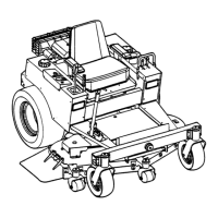
3.6 DECK REMOVAL (Continued from previous page)
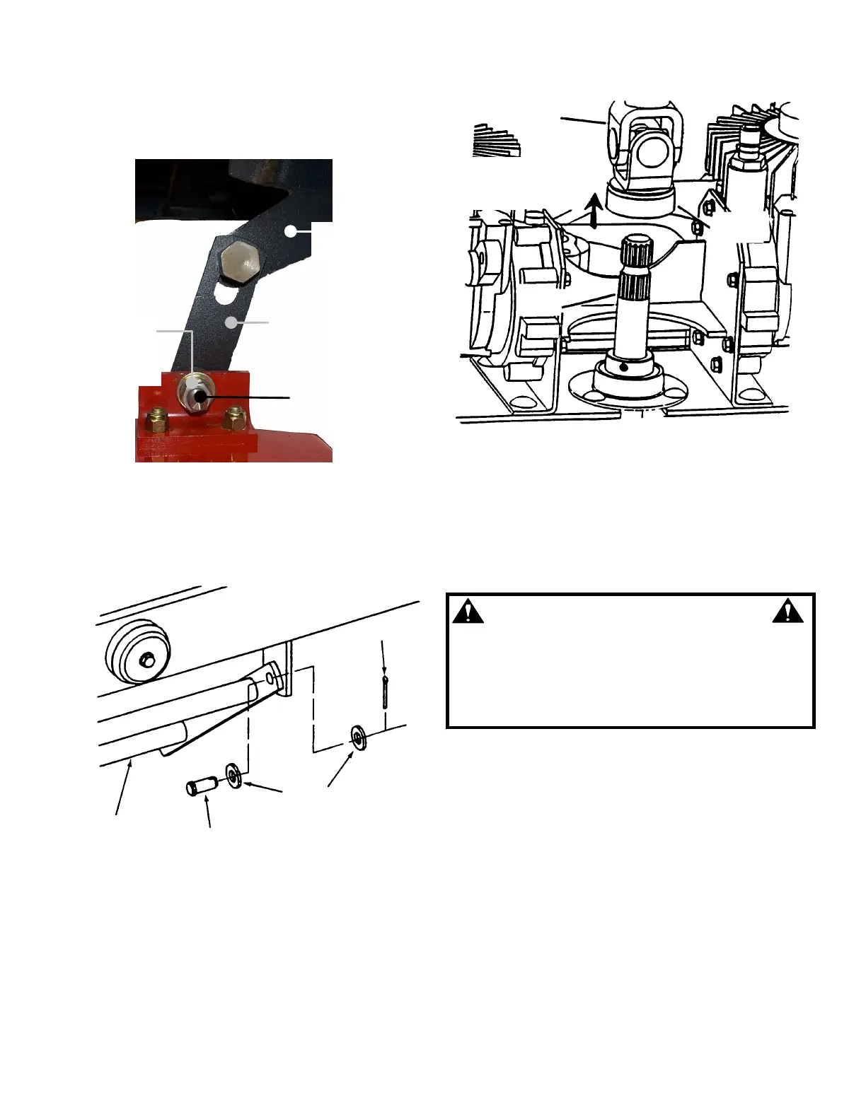
5. Remove shoulder bolts, washers and nuts from
rear lift arm. See Figure 3.11.
FIGURE 3.11
6. Disconnect pull bar from front axle by removing
clevis pins and cotter pins. See Figure 3.12.
FIGURE 3.12
7. Pull lock collar back and slide power transfer shaft
away from power take off shaft (located on power unit
below hydro pumps). See Figure 3.13.
FIGURE 3.13
IMPORTANT: Mower deck is extremely heavy. Be very
careful when removing deck from power unit.
8. Remove wooden blocks from underneath deck and
roll/slide deck from underneath power unit.
WARNING
DO NOT attempt any maintenance, adjustments or
service with engine running. STOP engine. STOP
blades. Set brake. Remove key. Remove spark plug
wires and secure away from spark plugs. Engine and
components are HOT. Avoid serious burns, allow
sufficient time for all parts to cool.
3.7 POWER TRANSFER SHAFT REMOVAL
Engage parking brake. Turn engine “OFF” and
remove key. The power transfer shaft connects the
power unit to the mower deck. The shaft is
telescoping for easy removal. Slide locking collar
back toward mower deck and shaft will slide off. See
Figure 3.13.
FRONT AXLE
PULL BAR
CLEVIS PIN
WASHERS
COTTER PIN
TRANSFER
SHAFT
LOCK
COLLAR
TAKE OFF
SHAFT
REAR
LIFT ARM
REAR LINK
PLATE
SHOULDER
BOLT,
WASHER &
NUT
THREADED
END
 Loading...