Do you have a question about the Snapper 5241 and is the answer not in the manual?
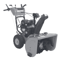
This document serves as the Safety Instructions & Operator's Manual for Snapper Snow Throwers, specifically covering models 5241, 8241, 8261, and 10301. It is designed to guide users through the safe and effective operation, as well as routine maintenance, of these two-stage snow throwers. The manual emphasizes the importance of understanding the equipment's potential dangers if used improperly and highlights that successful accident prevention relies on the operator's full cooperation.
The primary function of these Snapper machines is to clear snow from various surfaces. They are designed to provide long and satisfactory service, making snow removal more efficient and less strenuous. The snow throwers feature a collector auger system that gathers snow and an impeller housing that discharges it through a chute, which can be controlled to direct the snow stream.
Before operating the snow thrower, the manual stresses the importance of thorough preparation. This includes reading the manual to familiarize oneself with all controls, paying attention to decals on the engine and snow thrower, and wearing appropriate protective clothing, such as a face mask and boots for maximum footing on slippery surfaces. Users are advised to survey the area to be cleared beforehand, removing any objects like doormats, sticks, toys, wires, or rocks that could be hurled or jam the machine. Planning where snow is to be blown is crucial to avoid property damage or personal injury.
The snow throwers are equipped with several key controls for operation. The BLOWER CLUTCH HANDLE on the right handlebar engages the auger blades and impeller fan, while the TRACTION CLUTCH HANDLE on the left handlebar controls forward and reverse motion. Releasing these handles quickly stops the respective functions, with the blower auger and impeller stopping within five seconds for safety. The DISCHARGE CHUTE CONTROL allows the operator to adjust the direction of the snow discharge, and the DISCHARGE DEFLECTOR CAP can be repositioned to control the throwing distance.
Starting the engine involves moving the THROTTLE CONTROL to the FAST position and using the choke as instructed in the engine manual. Models may feature either rope starting or electric starting. For electric start models, a 120-volt plug-in system or jump start option is available. A brief warm-up period outdoors is recommended to avoid stalling a cold engine.
During operation, the FORWARD-REVERSE DIRECTIONAL CONTROL is used to select the desired traction speed. It is advised to start in a slow speed to ensure safe footing and adjust as needed to avoid overloading the blower housing, which could lead to clogging. If clogging occurs, operators are instructed to release both clutch handles, and as an additional precaution, stop the engine and remove the spark plug wire before attempting to clear the snow.
The manual also provides guidance on stopping the machine. Before completely stopping, it's recommended to move the unit to a cleared area, release the traction clutch handle, and run the engine at top speed with the blower clutch handle depressed to clear the housing of slush and snow. This prevents freeze-up of the impeller for the next start. To stop the engine, the ignition key should be removed, or the throttle control moved to the OFF or STOP position.
Safety is a paramount concern, with specific warnings against allowing children in the operating area or operating the machine without proper instruction. Operators are advised to avoid clearing steep slopes or areas where footing is doubtful and to clear snow across the face of slopes whenever possible. The engine should be stopped and the key removed if the unit is left unattended.
Routine maintenance is essential for the longevity and performance of the Snapper Snow Thrower. The manual details several lubrication services. The engine's lubrication requirements are covered in the separate Engine Manual. The snow thrower unit itself has six grease fittings: four on the augers and two on the auger shaft bearings. These should be greased once a year, preferably at the end of the winter season, to prevent rust and ensure smooth operation. The auger shear bolts should be removed during this process to allow grease to work along the auger shaft.
General lubrication points include spreading a light coating of grease on the chute crank worm and the underside of the gear ring at the base of the discharge chute. Oil should also be squirted into the gap between the discharge chute and the blower housing flange. Cranking the chute back and forth helps spread the lubricant evenly. Removing and greasing the axle shafts at the end of the season is also recommended to prevent rust and facilitate wheel movement.
The auger-impeller gearbox has a lube checkpoint at the front. The oil level in the gearbox should be checked every 25 hours of operation or whenever the engine oil level is checked. The oil should be even with the lower edge of the check hole when the thrower is on a flat, level surface, and the same weight and grade of oil specified for the engine crankcase should be used to top it off.
The CHUTE CRANK SERVICE section explains how to adjust the chute crank if it doesn't operate smoothly after lubrication. This involves loosening nuts on the crank worm bracket and repositioning it relative to the chute gear ring.
BELT SERVICE is also covered. Belts do not require specific interval attention but should be checked if performance deteriorates due to slippage. Before working on belts, the engine must be stopped, and the spark plug wire disconnected. The manual notes that blower rotation should cease within five seconds of releasing the clutch handle; if not, the cable may be too tight, or the idler return spring may need attention. Tension on the traction drive belt is automatically maintained by an idler spring, while the blower drive belt tension can be adjusted by repositioning the idler pulley.
CLUTCH CABLE ADJUSTMENT is crucial for proper operation. Both clutch cables should be completely slack when the handles are released and tight when fully depressed, with the springs deflecting 3/8". Adjustments involve repositioning "S" hooks on the cable to different chain links.
The SKID SHOE ADJUSTMENT allows operators to raise or lower the blower housing to clear different surfaces. Lowering the shoes provides clearance over gravel or rough surfaces, while raising them allows for clearing down to smooth paved surfaces. The skid shoes can also be installed upside down for better tracking on icy or hard-packed surfaces.
Finally, the SCRAPER BLADE is an adjustable component on the leading edge of the collector housing, designed to prevent wear and damage to the housing. As it wears down, it can be adjusted downward by loosening retaining nuts. It should be replaced if badly nicked or if it can no longer be adjusted below the housing's edge.
For replacement parts or service assistance, users are directed to contact their Snapper Dealer, providing the model and serial numbers found on the nameplate. Complete Parts and Service Manuals are also available for purchase.
| Engine Type | 4-Cycle OHV |
|---|---|
| Clearing Width | 24 inches |
| Auger Material | Steel |
| Skid Shoes | Adjustable |
| Speed Settings | 2 Reverse |
| Engine | 208cc |
| Stages | 2-stage |
| Starter | Recoil |
| Warranty | 2-year limited |