38
www.SnapperPro.com
Maintenance
A
A
A
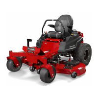
Figure 42. Checking The Blade Height Measurement
Deck Leveling Adjustment
Before adjusting the deck level, the deck lift rod timing
must be checked and/or adjusted.
Determining if the Deck Leveling Needs to be
Adjusted:
WARNING
Avoid Injury! Mower blades are sharp.
Always wear gloves when handling blades or
working near blades.
1. Park the unit on a flat, level surface. Disengage the
PTO, engage the parking brake, turn the ignition
switch to OFF, and remove the ignition key.
2. Lock the deck lift pedal in the TRANSPORT
position. Place the cutting height adjustment pin in
the 4” position and lower the deck lift pedal until the
deck lift arm contacts the cutting height adjustment
pin.
3. Verify that the tires are inflated to the correct
pressures.
4. Verify that the mower blades are flat, and not
bent or broken. A bent or broken blade must be
replaced.
5. See Figure 42. Position the mower blades to that
they face front-to-back.
6. Measure the front tip (A) of the blade from the
cutting edge to the ground.
7. Measure the rear tip (A) of the blade from the
cutting edge to the ground.
8. Repeat the process on the other side of the
machine.
• the front measurements should equal 4” (10,2 cm).
• the rear measurements should equal 4-1/4” (10,8
cm).
If the measurements do not equal the
measurements as listed above, adjust the deck
leveling.
Deck Leveling Adjustment - 61” Models:
1. Place the deck height adjustment pin in the 4” (10,2
cm) position.
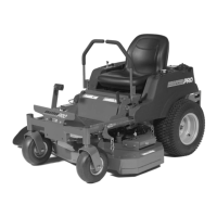
2. Place 2 X 4 blocks (A, Figure 43) under each
corner of the mower deck with the 3-1/2” sides
being vertical. Place a 1/4” (0,64 cm) thick spacer
(B) on the top of the rear blocks.
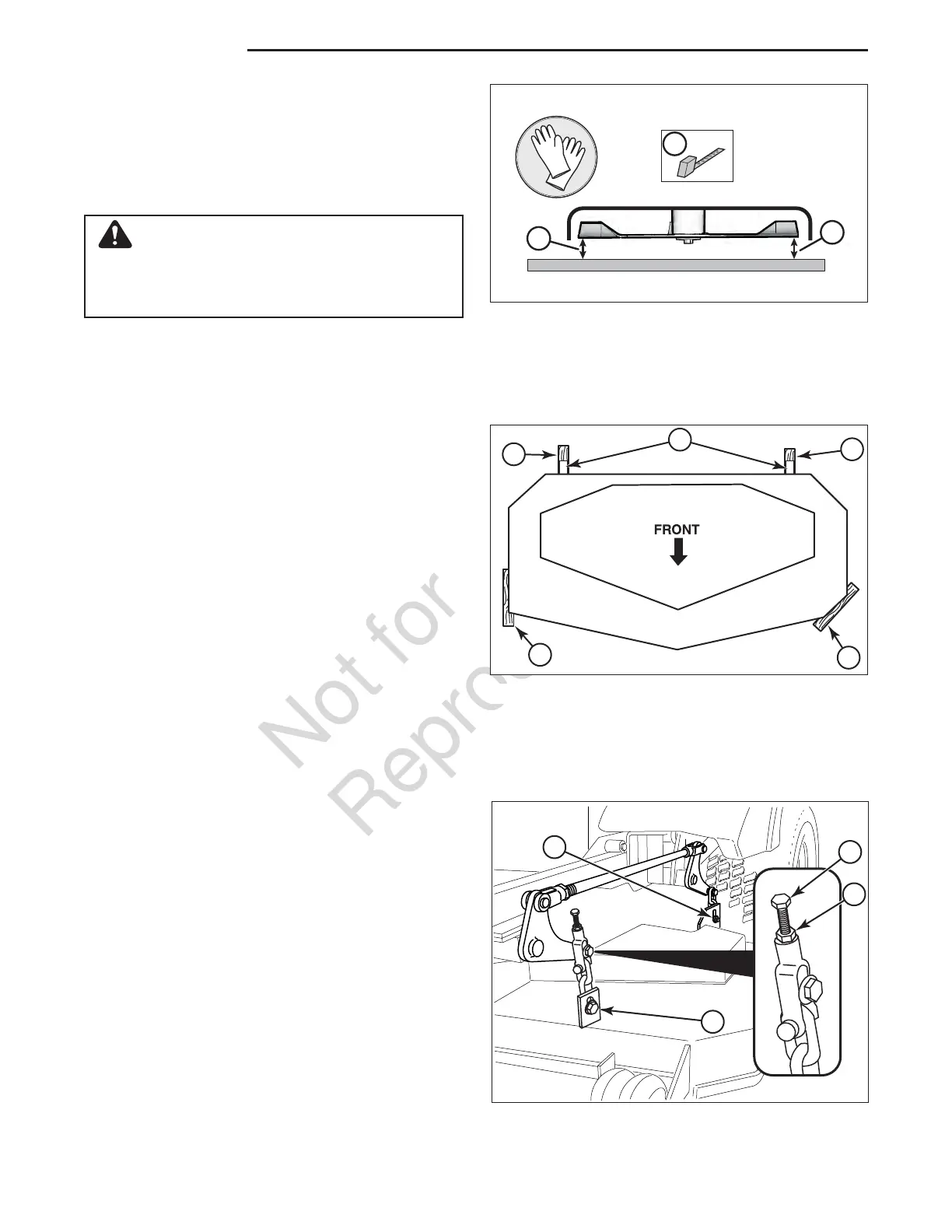
3. Loosen the nuts (A, Figure 44) and allow the front
of the deck to rest on the 2 X 4’s. Slide the chains
in the slots until the chains are tight and tighten the
nuts.
4. Loosen the nuts (B) and allow the rear of the deck
to rest on the 2 X 4’s and 1/4” spacers. Slide the
chains in the slots until the chains are tight and
A
A
A
A
B
Figure 43. 2 x 4 and 1/4” Spacer Locations
Figure 44. Deck Leveling Adjustment - 61” Models
C
D
B
A