17
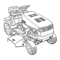
Operating the Tractor
A.
B.
A.
B.
Figure 8. Auxiliary Hydraulics
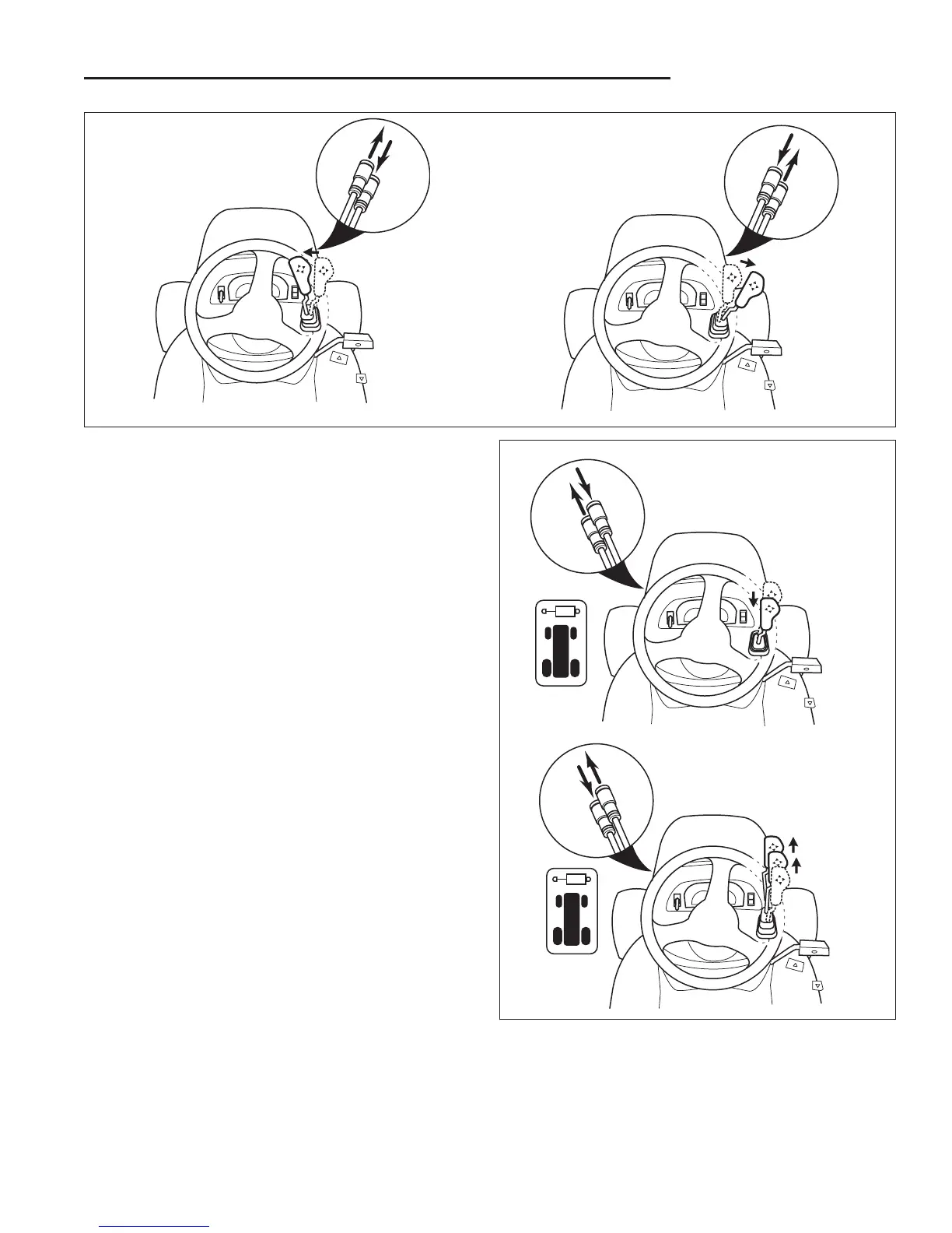
A. Lift
B. Lower
Figure 7. Auxiliary Hydraulics
A. Angle Left
B. Angle Right
Using Auxiliary Hydraulics
The attachment lift control is also used to control attach-
ments that use the tractor’s auxiliary hydraulic couplers
located on the right and left front frame rails. The left set
of quick couplers is activated when the front / rear
hydraulic switch is turned to the FRONT position (this
disables the inboard hydraulic cylinder).
Moving the control lever to the left (A, Figure 7) angles
the attachment left. Moving the lever right (B, Figure 7)
angles the attachment right.
Pulling the lever back raises the attachment lift (A, Figure
8). Pushing the lever forward to the first detent lowers
the attachment lift (B, Figure 8). Pushing the lever for-
ward to the second detent locks the control in “float”
position, allowing the lift mechanism to float up and
down.
Many approved attachments have color coded quick
couplers to aid in installation. Match the tractor quick
coupler with the like colored attachment quick coupler.