Seat and Ground Speed Lever Adjustments
The seat and ground speed levers should be adjusted
so that operator’s elbows are supported by the arm rests
when his/her hands are on the controls, and the ground
speed levers can be moved through their full range of
motion without contacting the operator’s legs.
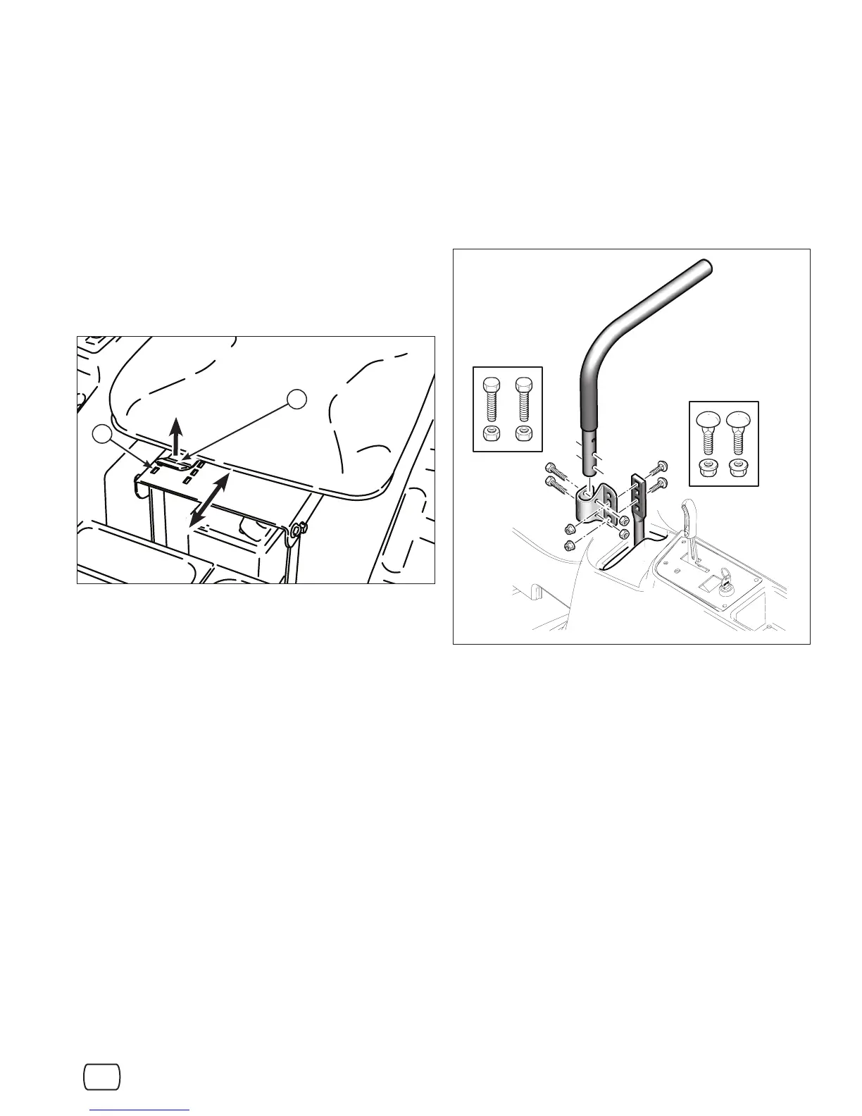
Seat Position Adjustment
Lift the seat adjustment lever (A, Figure 13). Slide the
seat forward or backward to the desired position, then
lower the seat adjustment lever. Make sure the lever
locks into the locking slots () in the seat base.
Figure 13. Seat Adjustment
A
13 lb-ft
(18 Nm)
13 lb-ft
(18 Nm)
Figure 14. Ground Speed Lever Adjustment
Ground Speed Lever Adjustment
Remove the ground speed lever mounting hardware
and bracket (see Figure 14). Move the levers to the
desired height using the adjustment holes. The bolts
need to be spaced so there is a hole open in between.
Reinstall the bracket and mounting hardware to the
levers.
23
en
6 lb-ft
(8 Nm)
13 lb-ft
(18 Nm)