Section 3- MAINTENANCE
3.5 ANNUALLY (END OF EACH SEASON)
(Continued from previous Page)
3.5.2. FUEL FILTER
Service fuel filter as instructed below. Turn key to
"OFF" position. Engine MUST be stopped and MUST
be cold before removing filter. Clamp fuel line to
prevent fuel spillage or perform filter change when
fuel tank and fuel line are empty.
1. Remove hose clamps from fuel filter.
2. Remove fuel lines from filter. Discard filter.
3. Install new fuel filter. Reinstall hose clamps. See
Figure 3.8.
FUEL FILTER
I
DIRECTION OF
FUEL
FUEL
HOSE
REINSTALL
CLAMPS AS
SHOWN
FIGURE 3.8
3.6 DECK REMOVAL
Move power unit/mower deck to an area where the
mower deck is to be disconnected. Turn engine
"OFF" but leave key switch in the "ON" position.
Engage parking brake.
1. The rear of deck must be raised up and both jack
shafts moved down to the lowest position and both
locking pins inserted.
2. Using deck lift switch, lower deck down to rest on
jack stands.
3. The hitch latch pins are shown in the latched
position. The latched position locks the deck lift arm
into position. See Figure 3.9.
HITCH LATCH PIN
SHOWN IN LATCHED
OR LOCKED
!/Y / DECK POS,T,ON
_'/ _ LIFT ARM HITCH /.
Ie LATCH
(_, PIN
7-H,TCHPLA -E _
--7
q--.: -.LTT.
FIGURE 3.9
13
3.7
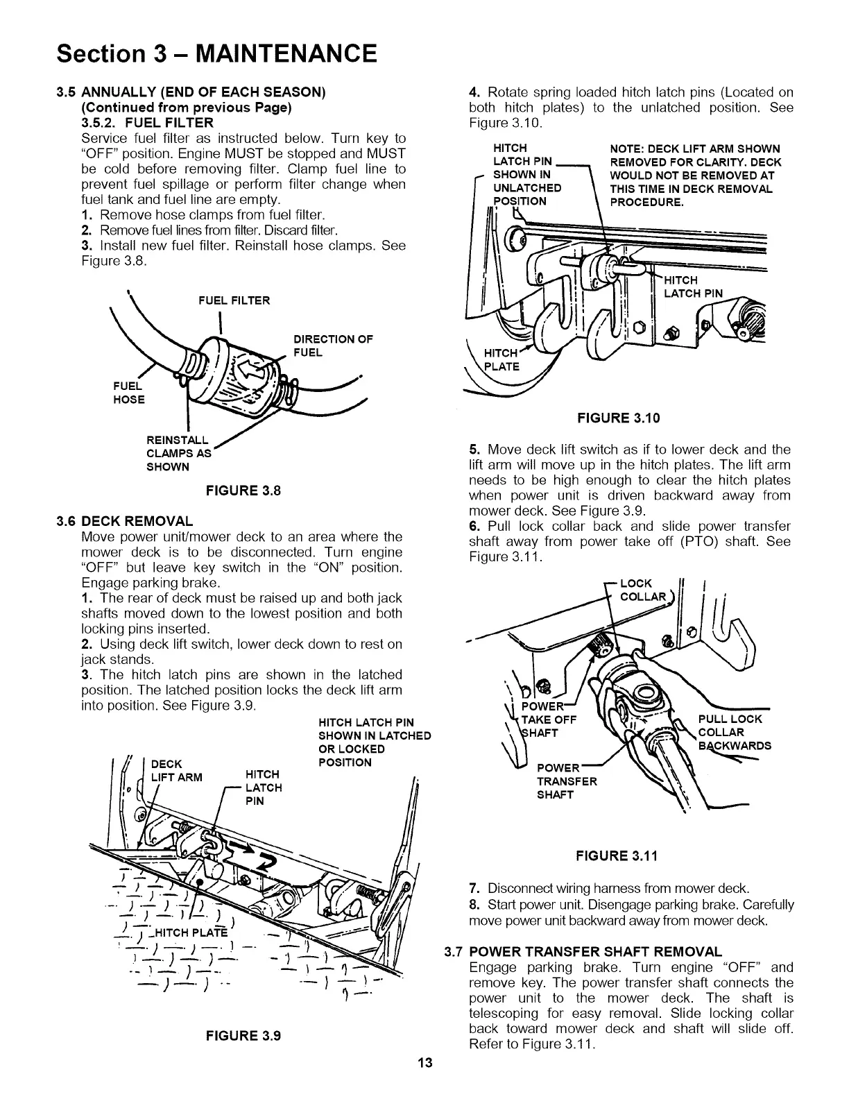
4. Rotate spring loaded hitch latch pins (Located on
both hitch plates) to the unlatched position. See
Figure 3.10.
HITCH
LATCH PIN
SHOWN IN
POSITION
NOTE: DECK LIFT ARM SHOWN
REMOVED FOR CLARITY. DECK
WOULD NOT BE REMOVED AT
THIS TIME IN DECK REMOVAL
PROCEDURE.
LATCH PIN
FIGURE 3.10
5. Move deck lift switch as if to lower deck and the
lift arm will move up in the hitch plates. The lift arm
needs to be high enough to clear the hitch plates
when power unit is driven backward away from
mower deck. See Figure 3.9.
6. Pull lock collar back and slide power transfer
shaft away from power take off (PTO) shaft. See
Figure 3.11.
LOCK I
;HAFT
POWER
TRANSFER
SHAFT
PULL LOCK
COLLAR
B_A_..ARR DS
FIGURE 3.11
7. Disconnect wiring harness from mower deck.
8. Start power unit. Disengage parking brake. Carefully
move power unit backward away from mower deck.
POWER TRANSFER SHAFT REMOVAL
Engage parking brake. Turn engine "OFF" and
remove key. The power transfer shaft connects the
power unit to the mower deck. The shaft is
telescoping for easy removal. Slide locking collar
back toward mower deck and shaft will slide off.
Refer to Figure 3.11.