Page | 8
Part# 210 / 210-BRD
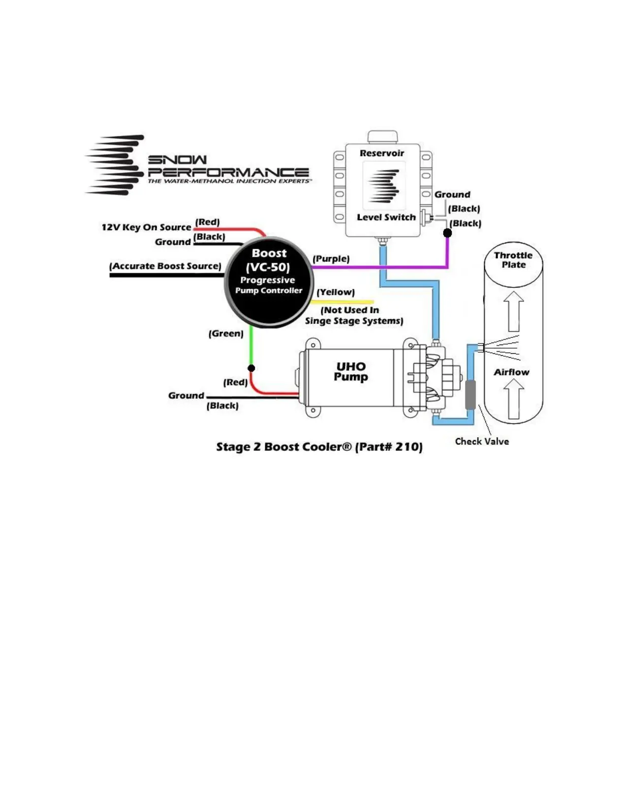
Wiring Diagram
Step 1 VC-50 Wiring/Boost Source
Step 1: Mount controller in desired location using a 52 mm gauge pod.
Step 2: Slide boost hose (black silicon hose supplied in kit) over the black boost line coming from the
controller and sure with a wire tie. Connect other end of black silicon hose to accurate boost source
using included boost “T” fitting.
Step 3: Using preferred electrical fitting connect BLACK wire to good ground location.
Step 4: Using preferred electrical fitting connect GREEN wire to Pump RED power wire.
Step 5: Using preferred electrical fitting connect PURPLE wire to one level switch black wire. Using
preferred electrical fitting connect other level switch black wire to good ground location. These wires are
interchangeable and either one can connect to controller/ground.
Step 6: Using preferred electrical fitting connector connect RED wire to 12Volt key on power source.
Step 7: YELLOW wire is not used in this install and can be tied out of the way.