13EN
#(1(2 Ű 2.".,$"
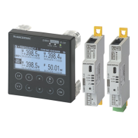
4.2. Presentation of associated current sensors
5@QHNTRSXODRNEBTQQDMSRDMRNQR@QDBNMMDBSDCSNSGD#(1(2 RNKHCBNQD3$ROKHSBNQD31H31NQkDWHAKD
3%3GDU@QHDSXADSVDDMSGDRDRDMRNQRLD@MRSGDXB@MAD@C@OSDCSN@MXSXODNEMDVDWHRSHMFNQGHFGBTQQDMS
existing installation. The DIRIS A-40 recognizes the sensor size and type. In addition, combining them means
SGDNUDQ@KK@BBTQ@BXNESGD#(1(2Ű BTQQDMSRDMRNQLD@RTQDLDMSBG@HMB@MADFT@Q@MSDDCNUDQ@K@QFD
measurement range.
#(1(2Ű
Current
sensors
TE, TR or TF
%NQBNMMDBSHMFSGDBTQQDMSRDMRNQR TRD2.".,$" B@AKDRNMKX1) RSQ@HFGSB@AKDR SVHRSDCO@HQ
TMRGHDKCDCŰ5¦"¦"
It is recommended that all the current sensors are installed in the same direction.
Connection cables for current sensors:
RJ12
connection
cables
Cable length (m)
1 2
ŮLQDDK
connectors*
Number of
cables
Part
number Reference Reference Reference Reference Reference Reference Reference Reference
1 - - - - - - 4829 0602 4829 0603 4829 0601
3 4829 0580 4829 0581 4829 0582 4829 0595 4829 0583 4829 0584 - - -
4 4829 0596 4829 0588 4829 0589 - - -
6 4829 0590 4829 0591 4829 0592 4829 0597 4829 0593 4829 0594 - - -
6GDMOQNCTBHMFB@AKDRCNMNSDWBDDC@L@WHLTLKDMFSGNELDSQDR