9
Installation and Operation
This section describes the final configuration as well as operation details for the PSX series power supplies.
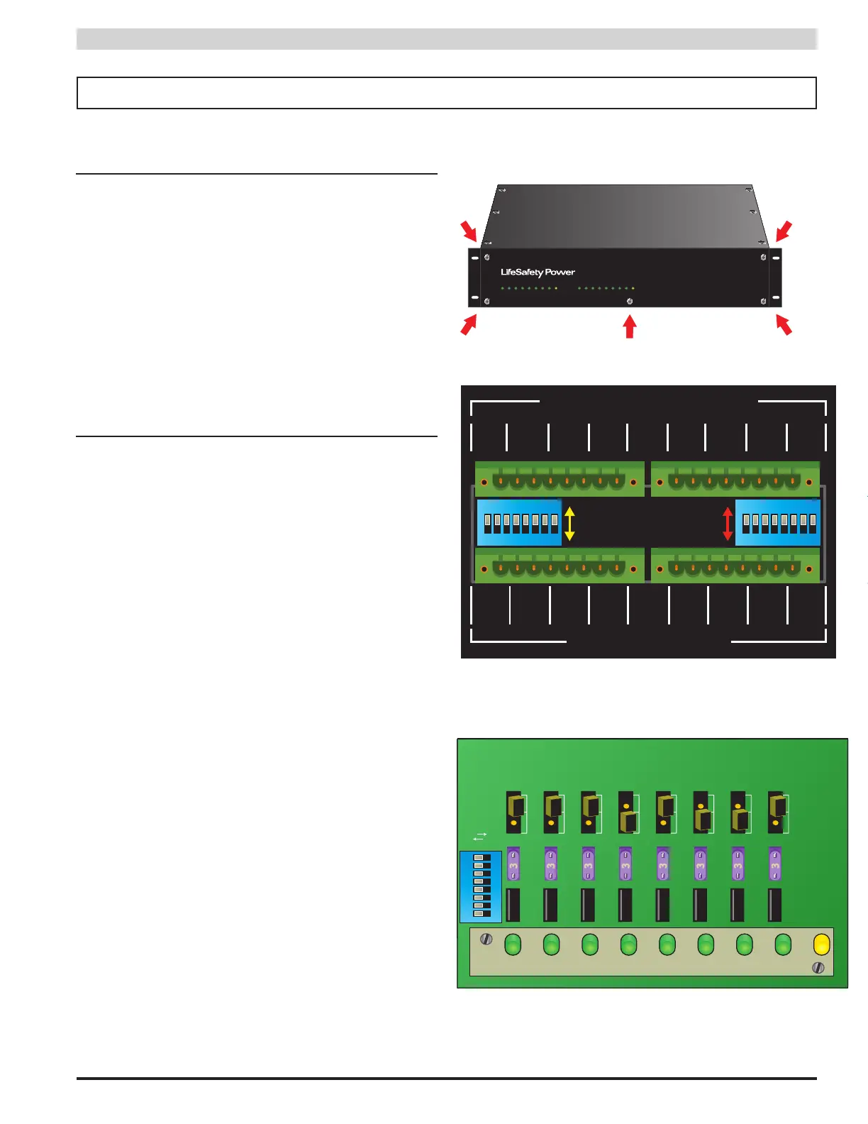
3.1 Removing the Faceplate of the Enclosure
Use the following steps to remove the faceplate of the rack-
mount enclosure and gain access to the front boards.
1. Remove and retain the five philips head 6-32 screws
from the faceplate. DO NOT remove the four 10-32
screws securing the enclosure to the rack.
2. Carefully remove the faceplate and set it aside in a
safe location
When configuration is complete, reverse the removal pro-
cedure to replace the cover, taking care to align the LEDs
with the holes in the faceplate (See figure 7).
3.2 Configuring the Zones - PSX-ISUSE
Input Selection (see Figure 8)
These switches are used to select a normally open or normally
closed input for each zone. Switch 1 sets zone 1, switch 2 sets
zone 2, and so on. Adjust this switch so that the zone's output
LED is FLASH ING when the door is unlocked.
•OFF(NC/FailSafe) Set this switch to OFF for a NC contact
input (contact OPENS to unlock door) or for a voltage input
where the voltage is REMOVED to unlock the door.
•ON(NO/FailSecure) Set this switch to ON for a NO contact
input (contact CLOSES to unlock door) or for a voltage input
where the voltage is APPLIED to unlock the door.
FAI Selection (see Figure 8)
These switches enable or disable FAI for the selected zone.
Switch 1 sets zone 1, switch 2 sets zone 2, and so on.
•ON(FAIEnabled)When this switch is set to ON, the zone's
output will invert when the FAI input is active. This is typically
used to drop power to maglocks on a fire alarm condition.
•OFF(FAIDisabled) When this is set to OFF, FAI will have no
effect on the zone's output.
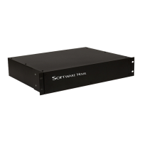
Output Selection (see Figure 9)
These switches are used to select a fail-safe or fail-secure out-
put for each zone. Switch 1 sets zone 1, switch 2 sets zone 2,
and so on. Set this switch so that the door is UNLOCKED when
the zone output LED is flashing (Zone Active).
•ON(FailSecureOutput) By setting this switch to ON, the
zone's output terminals will output a voltage when the zone in-
put is activated.
• OFF (Fail Safe Output) By setting this switch to OFF, the
zone's output terminals will not output a voltage when the zone
input is activated. This posi tion is typically used for Mag Locks.
Section 3 – Configuration and Usage
A B
CONTROLLED OUTPUTS
CONTROL INPUTS
1
+
2 3 4
-
+
-
+
-
+
-
5
+
6 7 8
1 2 3 4 5 6 7 8
-
+
-
+
-
+
-
A B A B A B A B A B A B A B
1
ON
2
3 4 5 6
871
ON
2
3 4 5 6
87
N.O. INPUT
N.C. INPUT
Enable FAI
Disable FAI
2 3 4 5 6 7 8 F F1 10 11 12 13 14 15 169
Figure 8 - PSX-ISUSE Back Board
Figure 9 - PSX-ISUSE Front Board
Figure 7 - Faceplate
CH1 CH2 CH3 CH4 CH5 CH6 CH7 CH8
FLT
3
—
3
3
3
3
3
3
3
3
CH1 CH2 CH3
VOLTAGE SELECT JUMPERS
DC1
DC2
Fail-Safe
OUTPUT
Fail-Secure
OUTPUT
CH4 CH5 CH6 CH7 CH8
FLT
3
3
3
3
3
3
3
3
1
ON
2
3 4 5 6
87