10
PSX Rackmount Power Supply - Installation and Operation Manual
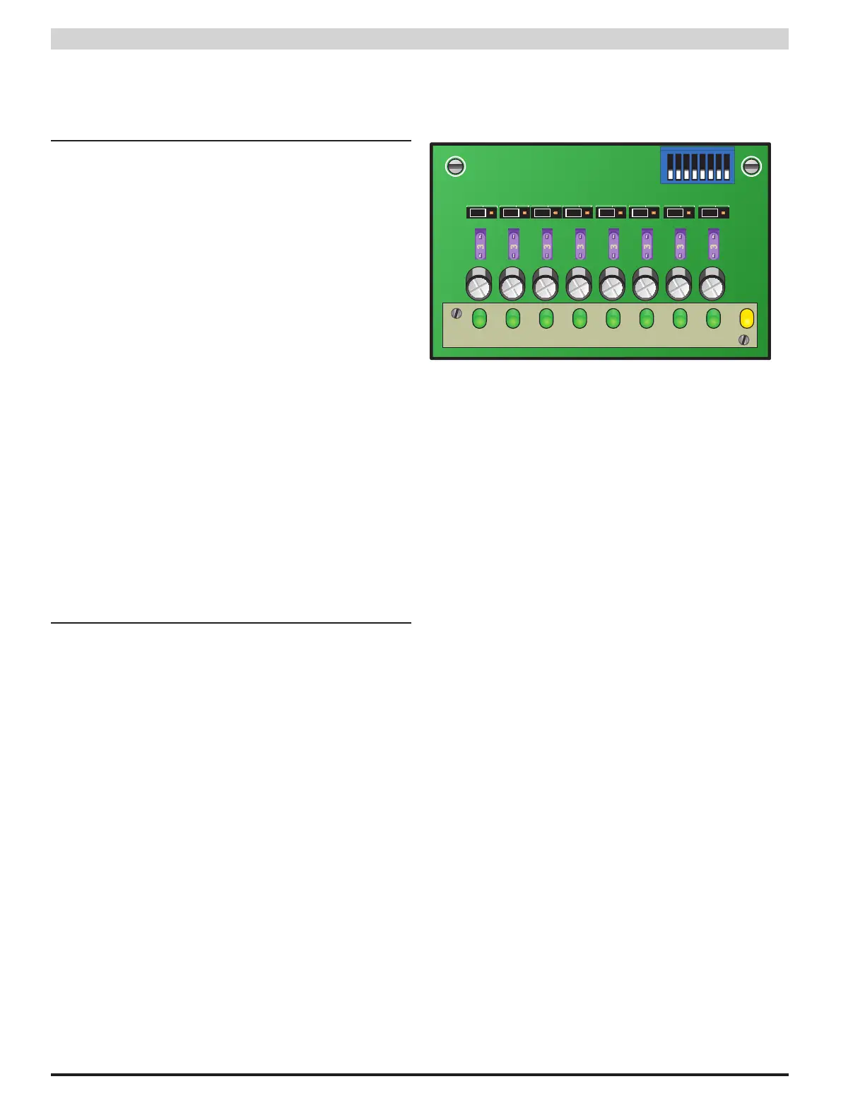
3.3 Configuring the Zones - PSX-ISU
Each output zone is configurable for one of two selections
which vary by model type. Selections are made by moving the
zone's corresponding jumper (marked as B1 and B2 on the PC
Board). See Figure 10
Single Supply Models
Each output is configurable for continuous or FAI con-
trolled. To set the operation of the FAI controlled outputs,
see Section 1.3.6.
• B1 (Left) Continuous Output (No FAI control)
• B2 (Right) FAI Controlled Output
Dual Supply Models
Each output is configurable for either internal power supply.
PSX#1 is the power supply on the left when looking from
the front and PSX#2 is the power supply on the right.
FAI control is provided on any distributed outputs set for
PSX#2 and the DC2 terminals of both PSX power sup-
plies.
• B1 (Left) PSX PS #1
• B2 (Right) PSX PS #2
3.4 Disabling Faults - PSX-ISU
Sometimes it is desirable to disable fuse fault detection for
individual zones. This allows removal of the fuse for spe-
cific unused zones or zones with unfinished wiring.
Faults can be disabled via the block of switches on the top
right of each front board (See Figure 2.2). Note that the
color of this switch block may vary. Switch numbers cor-
respond with zone numbers of the board (Switch 1 disables
faults for Zone 1, etc.). Switch settings are as follows:
• ON Fault Detection Enabled
• OFF Fault Detection Disabled
Figure 10 - PSX-ISU Front Board
CH1 CH2 CH3 CH4 CH5 CH6 CH7 CH8
FLT
1
2
3
4
5
6
7
8
3
3
3
3
3
3
3
3
—
1
B1 B2
JP1
2 3
 Loading...