11
Installation and Operation
ACF
ACF
DC2 –
DC2 +
BAT –
SF
SF
L
L
V –
I –
I
+
V +
BAT +
DC1 –
DC1 +
MAIN OUTPUT 2
9
+
10 11 12
-
+
-
+
-
+
-
13
+
14 15 16
-
+
-
+
-
+
-
9 10 11 12 13
14
15 16
A B
SF
SF
ACF
ACF
DC2 –
DC2 +
BAT –
L
L
V –
I –
I
+
V +
BAT +
DC1 –
DC1 +
MAIN OUTPUT 1
CONTROLLED OUTPUTS
CONTROL INPUTS
1
+
2 3 4
-
+
-
+
-
+
-
5
+
6 7 8
1 2 3 4 5 6 7 8
-
+
-
+
-
+
-
A B A B A B A B A B A B A B A B A B A B A B A B A B A B A B
CONTROLLED OUTPUTS
CONTROL INPUTS
Figure 13 - Ethernet Network Connection
Figure 11 - PSX-ISUSE Front Board
Figure 12 - PSX-ISU Front Board
CH1 CH2 CH3 CH4 CH5 CH6 CH7 CH8
FLT
3
—
3
3
3
3
3
3
3
3
CH1 CH2 CH3
VOLTAGE SELECT JUMPERS
DC1
DC2
Fail-Safe
OUTPUT
Fail-Secure OUTPUT
CH4 CH5 CH6 CH7 CH8
FLT
3
3
3
3
3
3
3
3
1
ON
2
3 4 5 6
87
CH1 CH2 CH3 CH4 CH5 CH6 CH7 CH8
FLT
1
2
3
4
5
6
7
8
3
3
3
3
3
3
3
3
—
1
B1 B2
JP1
2 3
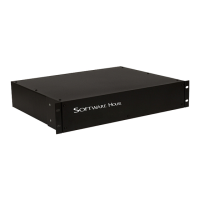
3.5 Status LEDs - PSX-ISUSE
Each front board has nine LEDs (see figure 11).
The eight green LEDs indicate the status of the zone’s output.
•OnSteady–Door Locked (Fuse or PTC Intact)
•Flashing–Door Unlocked (either due to Zone Input or FAI)
•Off–Fuse open or jumper missing
The yellow LED will light if a fault condition is detected by the
RC front board.
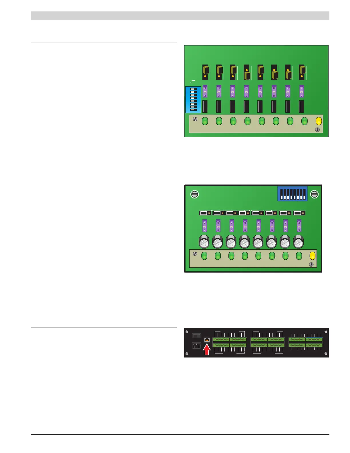
3.6 Status LED - PSX-ISU
Each front board has nine LEDs (see Figure 12). The eight
green LEDs give the voltage availability of the associated
zone. The yellow LED will light if a fault condition is detected.
3.7 Remote Access via Ethernet (All models)
PSX-N Series Rackmount power supplies use the optional Net-
Link board to allow access over the internet or local intranet via
the ethernet port on the back of the enclosure (see figure 13).
See the PSX NetLink manual for more information.
 Loading...