4
PSX Rackmount Power Supply - Installation and Operation Manual
Configuration internal to the rack mount enclosure is re-
quired on PSX series power supplies prior to installation
into a rack.
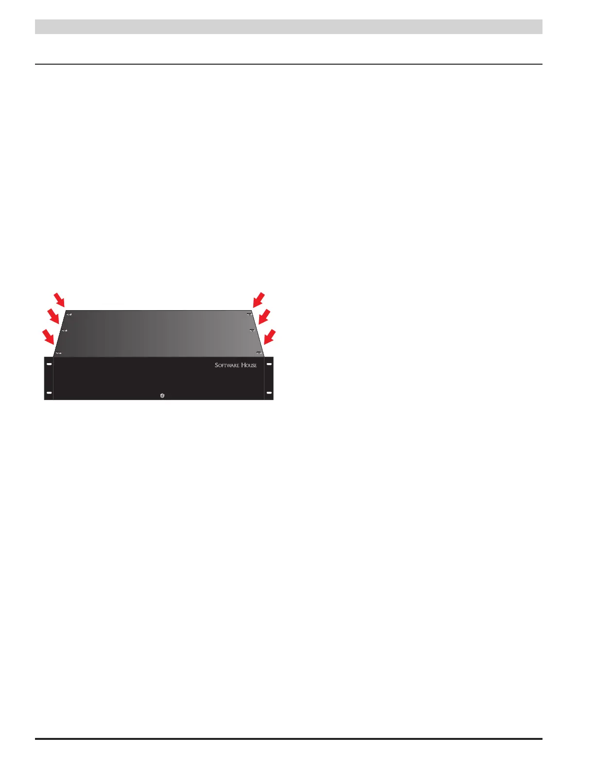
1.3.1 Removing the Top Cover of the Enclosure
Use the following steps to remove the top cover of the rack-
mount enclosure and gain access to the configurable settings.
(Figure 2)
1. Lay the enclosure flat on its bottom surface
2. Remove and retain the six philips head screws from
the top cover
3. Remove the top cover and set it aside in a safe location
When configuration is complete, reverse the removal pro-
cedure to replace the cover.
Figure 2 - The Top Cover Mounting Screws
1.3.2 Configuring for a 230VAC Input Voltage
The PSX series is factory set for a 120VAC input. If the PSX
is to be used with a 230VAC input, jumper JP1 must be cut on
ALL PSX power supplies internal to the PSX. (Figures 3 and 4).
See the PSX manual for more information.
i Failure to cut JP1 on both supplies when connecting to a
230VAC input will damage the system and void the warranty.
1.3.3 Setting the Output Voltages
The PSX series will contain one or two internal power sup-
plies, depending on model. The voltage may be set on each
PSX power supply for 12 or 24VDC .
After removing the top cover, set the output voltage of the
PSX power supplies by moving SW1 to either 12V or 24V
(See #3 in Figure 3).
See the PSX manual for more information on setting the
output voltage.
1.3.4 Enabling or Disabling Battery Presence Detection
Each PSX power supply may be set to detect a missing
battery set. To enable battery presence detection, place the
BATDET jumper ON. To disable battery presence detection,
remove the BATDET jumper, or place it on only one pin.
(See #2 in Figure 3)
1.3.5 Enabling or Disabling Earth Ground Detection
Each PSX power supply is able to detect earth ground
faults. To enable earth ground fault detection, place the
EARTH GND DET jumper ON. To disable earth ground fault
detection, remove the EARTH GND DET jumper or place it
on only one pin. (See #1 in Figure 3)
NOTE: Only one device in a system should have earth
ground fault detection enabled or conflicts may occur. In
addition, only ONE PSX power supply in a dual-supply PSX
system should have earth ground fault detection enabled or
a conflict may occur.
1.3.6 Changing the Operation of the Fault Contact Output
From the factory, PSX series supplies are shipped with a
normally open fault contact operation (relay contact closed
until a fault occurs).
This operation may be switched to a normally closed con-
tact (relay contact open until a fault occurs) by moving a
wire on each fault contact.
To switch from the default NO fault contact to a NC contact,
locate the fault output terminal strip on the PSX power sup-
ply. Identify the contact you want to change (SYS FLT or AC
FLT), loosen the terminal, remove the wire from the NO ter-
minal, move it to the NC terminal, and tighten the terminal.
NOTE: This must be done on BOTH power supplies in dual-
supply models.
1.3.7 Changing the FAI Operation
The DC2 output may be set to either power up when an FAI
is received or to drop power when an FAI is received by
changing the position of the DC2 fuse on the PSX board.
• DC2 NO Position - DC2 output has no voltage until a
valid FAI input signal is received.
• DC2 NC Position - DC2 output has voltage present in
the normal state. This voltage goes away when a valid
FAI input signal is received.
1.3 Internal Pre-Configuration