Do you have a question about the Sokkia CX-101 and is the answer not in the manual?
Explains various symbols used in the manual for warnings, notes, and prohibited actions.
Clarifies general terms and applies to specific models or provides context for illustrations.
Defines symbols like WARNING, CAUTION, and other advisory icons used in the manual.
Information on IP66 specifications and how to maintain waterproofing.
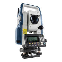
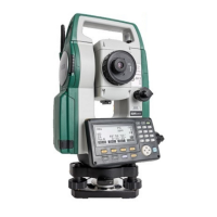
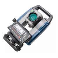
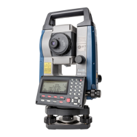
Identifies and labels all external parts of the CX series instrument with corresponding numbers.
Visual representation of the instrument's operational modes and navigation flow between them.
Details on Bluetooth communication capabilities, regulations, and setup procedures for wireless connectivity.
Explains fundamental operations like power on/off, display lighting, target type switching, and laser pointer usage.
Describes the various screens and status indicators displayed on the instrument's screen during operation.
Details how to access and use the Star Key menu for common measurement settings and program starts.
Step-by-step procedure for charging the instrument's battery using the specified charger.
Instructions on how to properly install and remove the battery pack from the instrument.
Procedures for centering the instrument over a survey point using optical or laser plummet.
Instructions for levelling the instrument using screen display or plate level for accurate measurements.
Guides through essential Bluetooth setup in Config mode for wireless communication.
Details on how to initiate and manage Bluetooth connections with other devices.
Procedures for entering known point data or outputting JOB data wirelessly.
Instructions for connecting the instrument to external devices using a communication cable.
Explains how to measure the included angle between two points by setting the horizontal angle to 0°.
Details on resetting and setting a specific horizontal angle value for measurement.
Describes how to output measured angle data to a computer or peripheral equipment.
Procedure to check the strength of the returned signal, especially for long-distance measurements.
Explains how to perform simultaneous distance and angle measurements.
Explains how to measure and output coordinate data to external devices.
Describes the Remote Measurement (REM) function for measuring heights of inaccessible points.
Detailed steps for inputting station coordinates, heights, and azimuth angles.
Procedure to calculate instrument station coordinates by observing known points.
Procedure to determine only the Z (height) coordinate of the instrument station.
Process for setting out points based on input coordinates, calculating angles and distances.
How to set out points based on horizontal angle and distance from the instrument station.
Procedure for setting out points where targets cannot be directly installed using REM measurement.
Steps to define a baseline by inputting coordinates or observing two points.
How to find required point coordinates by inputting length and offset based on a defined baseline.
Measures how far horizontally and vertically a point is from a baseline.
Finds required points along an arc by inputting arc length and offset based on the arc definition.
Defines a baseline by setting base point A and point B as the X-axis for point-to-line operations.
Projects a point onto a defined baseline and calculates distances.
Measures distances between multiple points using observation or coordinate input.
Describes how to change the last measured point to the next starting position for continuous measurement.
Records the instrument station as a reference point before starting surveying.
Calculates coordinates for center and width pegs for a straight line based on reference and IP points.
Calculates center and width pegs for a circular curve using BC and IP point coordinates.
Calculates center and width pegs for a spiral (clothoid) curve using reference point and curve properties.
Calculates center and width pegs for a parabola using reference point and curve properties.
Finds coordinates of cardinal, centerline, and width pegs using 3 IP points and curve properties.
Finds center and width pegs for a route with multiple curves, including cardinal and arbitrary point calculations.
Measures and sets out points along a cross-section of a road or linear feature.
Defines a baseline by setting base point A and point B as the X-axis for point-to-line operations.
Defines target point coordinates relative to a baseline and calculates instrument station data.
Stores instrument station coordinates, height, and other related settings in the current JOB.
Records backsight station data, including azimuth angle and measurements.
Stores both distance and coordinate data simultaneously under the same point name.
Displays and allows searching of recorded data within the current JOB.
Guides on selecting the current JOB and the Coordinate Search JOB for data management.
Instructions on how to clear data within a designated JOB and restore default naming.
Procedures for registering or deleting coordinate data for known points using key entry or external devices.
Procedures for saving, reading, and deleting codes used for data entry.
Steps to transfer JOB data (measurements, settings) to a host computer.
Instructions on how to properly insert a USB memory device into the instrument.
Procedures for saving JOB data (measurements, settings) onto a USB memory device.
Instructions on how to load known point data or codes from a USB device into the CX.
How to view file information, edit file names, and delete files on USB memory.
Explains parameter settings and how to change them within the Config Mode.
Explains settings related to the Electronic Distance Measurement (EDM) module.
Details how to assign functions to softkeys for efficient operation.
Instructions on how to change or set a password for instrument security.
Procedures for resetting instrument settings to factory defaults.
Procedure to check and adjust the plate level for instrument stability and accuracy.
Procedure to check and adjust the circular level for proper instrument leveling.
Explains how to check and cancel tilt zero point error to ensure accurate angle measurements.
Procedure to check and adjust the optical plummet for accurate centering.
Explains how to check and verify the additive distance constant for accurate distance measurements.
Procedures for checking and adjusting the laser plummet for accurate vertical alignment.
Lists the essential equipment included with the instrument package.
Lists and describes accessories sold separately that enhance instrument functionality.
Details various reflecting prisms, targets, and holders for distance and angle measurements.
Lists compatible batteries, chargers, and power supplies for operating the instrument.
Procedure to eliminate vertical circle 0 index inaccuracy for high-precision angle measurements.
Explains the need for and methods of atmospheric correction for accurate distance measurements.
Details the formulas and methods for correcting distance measurements for refraction and earth curvature.
| Brand | Sokkia |
|---|---|
| Model | CX-101 |
| Category | Measuring Instruments |
| Language | English |