Chapter 3: Power Optimizer Installation
SolarEdge Power Optimizers Installation Guide – MAN-01-00112-1.2
For mounting on rails with sliding nut fasteners, or on an un-grounded structure (such as a wooden
structure): Connect an equipment-grounding conductor to the grounding terminal according to the
supplied instructions (the terminal should be purchased separately
*
). The grounding terminal
accepts a wire size of 6-14 AWG, and must be sized for equipment grounding per NEC 250.122
requirements. Tighten the screws connecting the power optimizer to the frame and the grounding
terminal screw. Apply torque of 9.5 N*m / 7 lb*ft.
The metallic enclosure of the power optimizer must be grounded in accordance with the
requirements of the Local and National Codes.
L'enceinte métallique de l’optimiseur de puissance doit être mise à la terre en accord avec les
régulations locales et nationales..
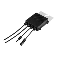
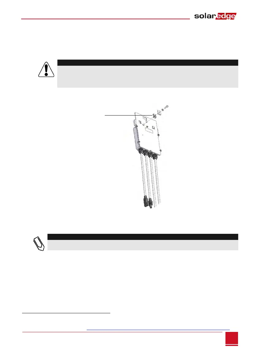
Figure 5: Power optimizer grounding terminal
For rest of the world – all power optimizers are double insulated and grounding is not required.
Record power optimizer serial numbers and locations, as described in Step 4, Providing Installation
Information on page 15.
6 Verify that each power optimizer is securely attached.
*
For additional information, refer to http://www.solaredge.com/files/pdfs/se-product-update-dcd-c-grounding-lug.pdf.
Optional grounding
terminal