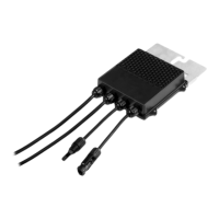
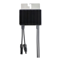
Power Optimizer
For Europe
P800p / P850 / P950 / P1100
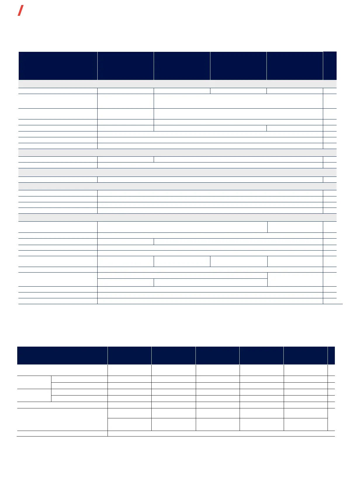
Power Optimizer Model
(Typical Module Compatibility)
P800p
(for up to 2 x 96-cell
5
PV modules)
P850
(for up to 2 x high
power or bi-facial
P950
(for up to 2 x high
power or bi-facial
P1100
(for up to 2 x high
power or bi- facial
onnection Method
Dual input for independently
Connected modules
Single input for series connected modules
Absolute Maximum Input Voltage (Voc at lowest
temperature)
Maximum Short Circuit Current per Input (Isc)
OUTPUT DURING OPERATION
(
POWER OPTIMIZER CONNECTED TO OPERATING SOLAREDGE INVERTER
)
OUTPUT DURING STANDBY
(
POWER OPTIMIZER DISCONNECTED FROM SOLAREDGE INVERTER OR SOLAREDGE INVERTER OFF
)
Safety Output Voltage per Power Optimizer
FCC Part 15, IEC 61000-6-2, and IEC 61000-6-3 - Class B, EN 55011 - Class A
IEC62109-1 (class II safety)
INSTALLATION SPECIFICATIONS
SolarEdge Inverters Three phase inverters SE16K & larger
(2)
Three phase inverters
SE25K & larger
Maximum Allowed System Voltage
129 x 168 x 59 / 5.1 x 6.61 x 2.32
129 x 162 x 59 / 5.1 x 6.4 x 2.32
Wire Length
0.16 / 0.52
0.16 / 0.52, 0.9 / 2.95,
1.3 / 4.26, 1.6 / 5.24
(4)
0.16 / 0.52, 1.3 / 4.26,
1.6 / 5.24
(4)
0.16 / 0.52, 1.3 / 4.26
(4)
m /ft
Wire Length
Portrait orientation: 1.2 / 3.9
2.4 / 7.8 m /ft
Landscape orientation: 1.8 / 5.9
Landscape orientation: 2.2 / 7.2
Operating Temperature Range
(5)
* For P850/P950 models manufactured in work week 06/2020 or earlier, the maximum Isc per input is 12.5A. The manufacture code is indicated in the Power Optimizer's serial number
Example: S/N SJ0620A-xxxxxxxx (work week 06 in 2020)
(1) Rated power of the module at STC will not exceed the Power Optimizer “Rated Input DC Power”. Modules with up to +5% power tolerance are allowed
(2) For compliance with EN 55011 class A (where required), installation shall be done with inverter 20kVA or larger, and comply with the requirements in the EMC section of the installation manual
(3) For other connector types please contact SolarEdge
(4) Longer inputs wire length are available for use with split junction box modules
(For 0.9m/2.95ft order P801/P850-xxxLxxx. For 1.3m/2.95ft order P850/P950/P1100 -xxxXxxx. For 1.6m/5.24ft order P850/P950-xxxYxxx)
(5) For ambient temperature above +70˚C/+158˚F power de-rating is applied. Refer to Power Optimizers Temperature De-Rating Technical Note for more details
PV System Design Using a
SolarEdge Inverter
(6)(7)(8)
230/400V Grid
SE25K*
230/400V Grid
SE27.6K*
230/400V Grid
SE30K*
230/400V Grid
SE33.3K*
277/480V Grid
SE33.3K*, SE40K*
Compatible Power Optimizers
P800p, P850, P950, P1100
P800p, P850, P950,
P1100
Minimum String
Maximum Continuous Power per String
Allowed Connected Power per String
(9)
(Permitted only when the difference in connected power
strings is 2,000W or less)
1 string - 15750 1 string - 16200
2 strings or
less - 15750
2 strings or
less - 17550
W
more - 18500
more - 18950
more - 20300
more - 18500
more - 20300
Parallel Strings of Different Lengths or Orientations
* The same rules apply for Synergy units of equivalent power ratings, that are part of the modular Synergy Technology inverter
(6) P800p/P850/P950/P1100 can be mixed in one string only with P800p/P850/P950/P1100
(7) For each string, a Power Optimizer may be connected to a single PV module if 1) each Power Optimizer is connected to a single PV module or 2) it is the only Power Optimizer connected to a single PV module in the string
(8) For SE25K and above, the minimum STC DC connected power should be 11KW
(9) To connect more STC power per string, design your project using SolarEdge Designer
1 string - 17550