Connecting the ACGrid to the Inverter
Use a five-wire cable for three phase connection. The maximum wire size for the input
terminal blocks is 16mm².
1. Turn OFF the AC circuit breaker.
2. Open the inverter cover: Release the six Allen screws and carefully move the cover
horizontally before lowering it.
CAUTION!
When removing the cover, make sure not to damage internal components.
SolarEdge will not be held responsible for any components damaged as a
result of incautious cover removal.
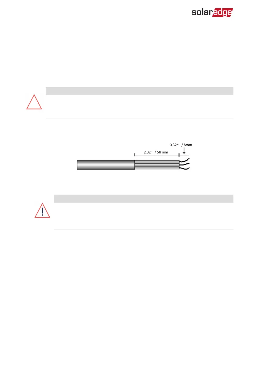
3.
Strip 58 mm / 2.32'' of the external cable insulation and strip 8 mm / 0.32'' of the
internal wire insulation.
Figure 12: Insulation stripping – AC (3-wire cable)
4.
Open the AC cable gland and insert the cable through the gland (see ).
WARNING!
Turn OFF the AC before connecting the AC terminals. If connecting
equipment grounding wire, connect it before connecting the AC Line and
Neutral wires.
5.
For SE25K, SE27.6K, and SE33.3K three phase inverters, attach the supplied Ferrite
bead to the AC wires:
1. Insert the AC wires through the supplied bead.
2. Connect the AC wires to the terminal blocks as described in the next steps.
3. Tighten the wires to the bead using the supplied T-wrap.
-Three Phase System Installation Guide MAN-01-00057-4.1
32 Connecting the ACGrid to the Inverter