EasyManua.ls Logo

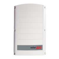
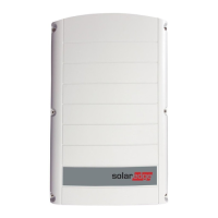
SolarEdge SE4000-16A

SolarEdge SE4000-16A
114 pages
To Next Page IconTo Next Page
Loading...
Installation Guide
SolarEdge System
Installation Guide
For Europe and APAC
Version 4.1

Table of Contents

Questions and Answers:

SolarEdge SE4000-16A Specifications

General IconGeneral
ModelSE4000-16A
Rated Output Power4000W
Protection ClassIP65
Warranty12 years
Nominal AC Power4000 W
AC Voltage240 V
CEC Efficiency97%
Operating Temperature Range-25°C to 60°C
Frequency60 Hz
CoolingConvection

Summary

Support and Contact Information

Contact SolarEdge Support

Contact details for technical support by region, including phone and email.

HANDLING AND SAFETY INSTRUCTIONS

Safety Symbols Information

Explanation of safety symbols used throughout the document and their meanings.

IMPORTANT SAFETY INSTRUCTIONS

General Safety Adherence

General warning emphasizing mandatory adherence to all handling and safety instructions.

Inverter Cover Safety Precautions

Warning about the risk of electric shock when opening the inverter cover.

AC Grounding and Wiring Safety

Ensuring proper grounding of the inverter AC power cable and wall outlet.

Qualified Personnel for Inverter Service

Inverter repair and testing must be performed by qualified service personnel only.

PV Panel and Rail System Safety

Caution against touching PV panels or rail systems when the inverter switch is ON.

SafeDC Voltage Compliance Requirements

Compliance with SafeDC voltage limits for system installation.

Unit Operation and Lifting Safety Guidance

Guidance on proper unit operation and lifting techniques for heavy objects.

Chapter 1: Introducing the SolarEdge Power Harvesting System

Installation Procedure Overview

Step-by-step guide for installing and setting up a new SolarEdge site.

Chapter 2: Installing the Power Optimizers

Power Optimizer Installation Safety

Notes and warnings applicable to power optimizer installation, including smart modules.

Optimizer Connector Compatibility Assurance

Warning about ensuring connector compatibility between modules and optimizers.

Step 1: Mounting the Power Optimizers

Power Optimizer Mounting Procedure

Detailed steps for mounting power optimizers to the support structure.

Step 2: Connecting a PV Module to a Power Optimizer

PV Module to Optimizer Connection Steps

Instructions for connecting a PV module to the input connectors of a power optimizer.

Step 3: Connecting Power Optimizers in Strings

Series Connection of Power Optimizers

Procedure for connecting power optimizers in series to form strings.

Unused Connector Sealing Warning

Warning to seal unused dual-input power optimizer connectors.

Step 4: Verifying Proper Power Optimizer Connection

Power Optimizer Connection Verification

Steps to verify the correct connection and polarity of power optimizers in strings.

Chapter 3: Installing the Inverter

Inverter Connector Handling Caution

Caution against resting inverter connectors on the ground to prevent damage.

Inverter Safety and Status Indicators

PVRSS Safety Warning

Warning regarding manual Rapid Shutdown (PVRSS) and inverter cover opening.

Mounting the Inverter

Inverter Mounting Instructions

Instructions for mounting the inverter, applicable for vertical and horizontal installations.

Heavy Object Lifting Safety Guidance

Guidance on lifting heavy objects to avoid strain or injury.

Saline Environment Installation Distance

Installation distance requirements from saline environments.

Chapter 4: Connecting the AC and the Strings to the Inverter

Connecting the AC Grid to the Inverter

AC Grid Connection via DC Safety Unit

Steps for connecting the AC grid to the inverter via the DC Safety Unit.

Inverter Cover Removal Caution

Caution regarding potential damage to internal components during cover removal.

AC Connection Wiring Warning

Warning to turn off AC before connecting terminals and connect grounding wire first.

Connecting the Strings to the Inverter

Chapter 5: Commissioning the Installation

System Activation Procedure Steps

Steps to activate the system, including verifying switch positions and inserting the activation card.

Electrical Shock Hazard Warning During Activation

Warning about electrical shock hazard when accessing internal wiring.

System Activation Procedure

Step 2: Pairing Power Optimizers to the Inverter

Power Optimizer Pairing Procedure

Procedure to logically pair power optimizers to their respective inverter.

High DC Voltage Warning Post-Pairing

Warning about high DC voltage and loss of 1V safety output after turning ON the inverter.

Step 3: Verifying Proper Activation

Activation Status Verification Checks

Checking system status indicators (LEDs, LCD) after activation.

Step 4: Reporting and Monitoring Installation Data

Installation Data Reporting Process

Steps for reporting and monitoring installation data, including connecting to the platform.

The Monitoring Platform

Monitoring Platform Capabilities Overview

Overview of the monitoring platform's capabilities for PV performance monitoring and alerts.

Chapter 6: User Interface Overview

LCD User Button Functions

Description of the four buttons for controlling the inverter's LCD menus.

Setup Mode Configuration Functionality

Setup Mode Configuration Steps

Performing basic inverter configuration in Setup mode.

Error Message Display on LCD

LCD Error Message Indication and Reference

Display of error messages on the LCD panel when problems occur.

Inverter Configuration - Setup Mode

Setup Mode via Internal LCD Buttons

Detailed steps for configuring the inverter using internal LCD buttons.

DC Voltage Safety Warning During Setup

Warning about DC voltage not being safe before it drops below 50V.

Status Screens - Operational Mode

Chapter 7: Setting Up Communication

Removing the Inverter Cover

Inverter Cover Removal Procedure

Procedure for removing the inverter cover for access to internal components.

DC Voltage Safety Warning During Cover Removal

Warning about DC voltage not being safe before it drops below 50V.

Creating an Ethernet (LAN) Connection

Ethernet Connection Procedure Steps

Steps for connecting the inverter to the monitoring platform via Ethernet.

Gland Sealing Cautionary Note

Caution regarding gland waterproof fitting for proper sealing.

Creating an RS485 Bus Connection

RS485 Bus Connection Procedure

Steps to create an RS485 bus connection for multiple inverters.

Verifying the Connection to Monitoring Server

Connection Verification Steps

Steps to check if the connection to the monitoring server has been successfully established.

Electrical Hazard Warning During Verification

Warning about electrical shock hazard when accessing internal wiring.

Appendix A: Errors and Troubleshooting

Troubleshooting Communication Errors

Troubleshooting communication issues, particularly Ethernet connection errors.

Troubleshooting Communication Errors

Power Optimizer Troubleshooting Guide

Power Optimizer Problem Diagnosis

Troubleshooting power optimizer issues like pairing failures and incorrect string voltage.

High Voltage Installation Warning

Warning about potentially high installation voltage and proceeding with care.

Appendix C: Connecting the AC and DC Strings to the DC Safety Unit

Connecting the Strings to the DC Safety Unit

DC String Connection Procedure Steps

Procedure for connecting DC strings to the DC input pairs of the DC Safety Unit.

Appendix D: SafeDC Functionality

SafeDC Explanation and Standards Compliance

Explanation of SafeDC functionality and compliance with disconnection standards.

External Fan Replacement Procedure

Capacitor Discharge Safety Warning

Warning about discharging capacitors before servicing or if panel is not visible.

Appendix F: Replacing and Adding System Components

Inverter Replacement Procedure

Step-by-step procedure for replacing an inverter.

Capacitor Discharge Safety Warning during Inverter Replacement

Warning about discharging capacitors before servicing or if panel is not visible.

Inverter Replacement Procedure

Replacing the DC Safety Unit

Adding, Removing, or Replacing Power Optimizers

Power Optimizer Management Procedure

Procedures for adding, removing, or replacing power optimizers in the system.

Appendix G: Determining the Circuit Breaker Size

Determining the Size of an Inverter Circuit Breaker

SolarEdge Support Contact Information

Contact SolarEdge Support Portal

Contact information and support portal for technical queries and assistance.

Related product manuals