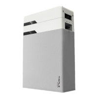
4. Installation
4. Installation
15
14
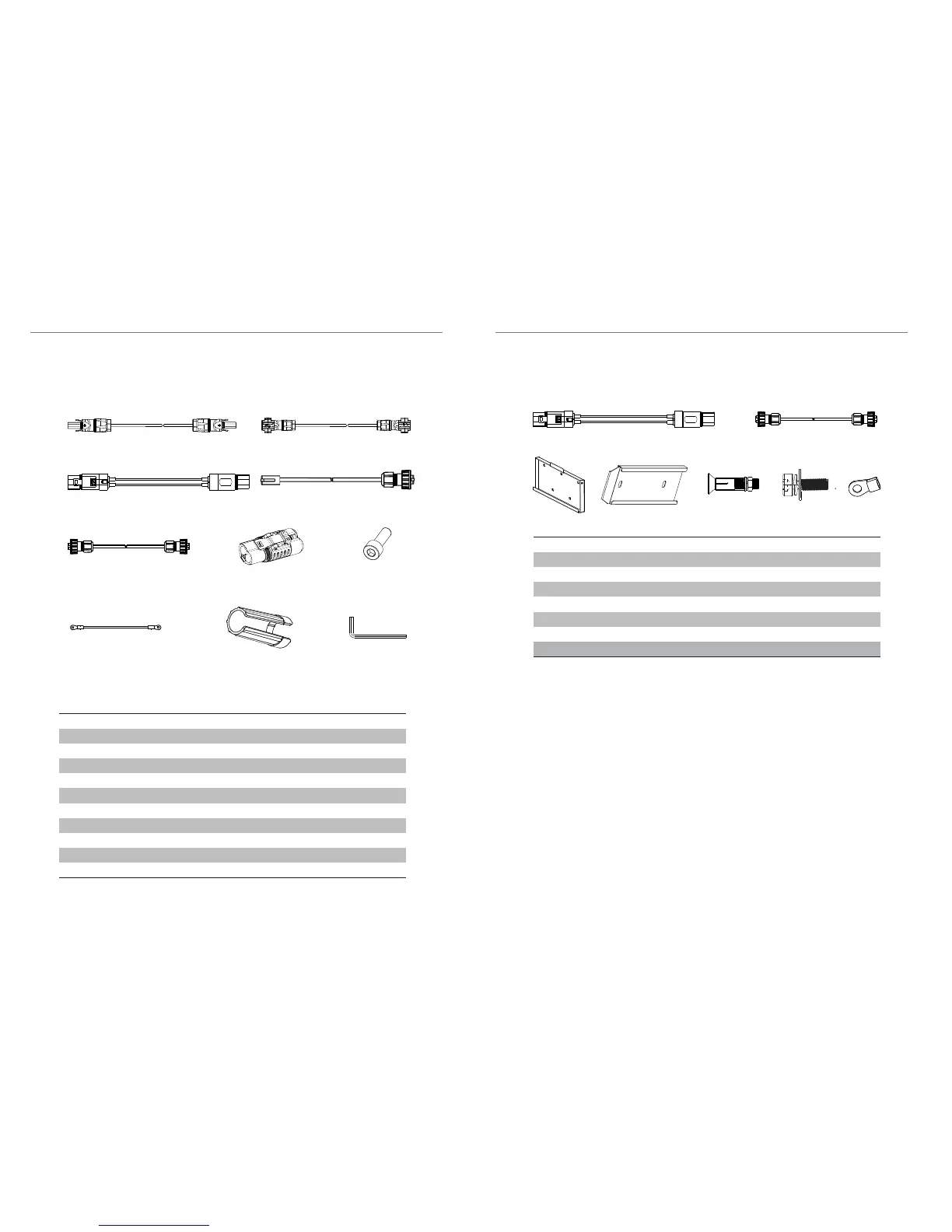
4.4.3 Packing List
A
B
C D
F
G
H
The table below lists the number of each component.
BMS (Master Box):
I
Object
A
B
C
D
E
F
G
H
I
J
Description
Charging cable (+)
Charging cable (-)
Power cable between BMS and battery module (120mm)
CAN communication cable (2m)
RS485 communication cable (120mm)
Short-circuit plug
M5 screw
Ground wire
Rotation wrench
L-type wrench
Quantity
1
1
1
1
1
1
4
1
1
1
E
J
A1
B1
E1 F1
C1
D1
Battery Module (T45/T63):
Quantity
1
1
1
1
5
1
2
Object
A1
B1
C1
D1
E1
F1
G1
Description
Power cable between battery modules (400mm)
RS485 communication cable (400mm)
Wall mounting backboard
Floor mounting backboard
Expansion screw sleeve
M6 screw
Ring terminal (for grounding)
G1