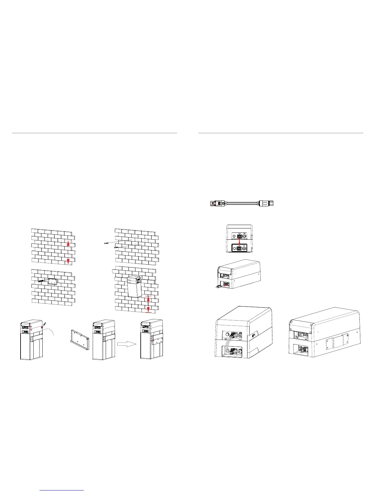
Wall mounting:
Make sure the wall is strong enough to withstand the weight of battery modules.
Step 1: fix the wall bracket (C1) on the wall
Ÿ Use the wall bracket as a template to mark the position of the 5 holes
Ÿ Drill holes with driller, make sure the holes are deep enough (at least 50mm)
for install and tight the expansion screw sleeves
Ÿ Install the expansion screw sleeves (E1) in the wall, and screw the bracket by
using the wrench.
Step 2: Remove the upper hanging board which has been installed already.
Step 3: Match the battery module with the wall bracket
Ÿ Transport the battery module to the wall bracket
Ÿ Hang the battery module over the wall bracket, move the battery module
close to it, and match it on the wall bracket
Step3: Lock the joint between hanging board and wall bracket with M6 screw(F1).
The following figure is the back view of wall mounting.
1m
300 mm
Note: Keep the distance from installation point to the floor less than 1m.
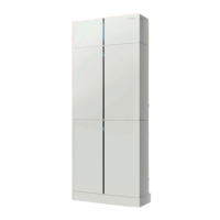
4.5 Cable Connection
4.5.1 Connecting Power Cables
For one battery module:
The color at both end of the power cable between BMS and battery module (C)
is orange, and this color is connected to XPLUG which is on the left side of the
BMS (Ⅱ) and battery module (Ⅰ’).
1. Plug either end of the power cable to XPLUG
on BMS (Ⅱ) and battery module (Ⅰ’). When
the metal sheet which is marked in red is
totally inserted and a click sound is heard, that
means the power cable is completely
connected.
2. Please make sure that both ends of the power
cable are connected to the correct connector,
which are on the left side of BMS and battery
module that shown in the figure.
3. After the battery module were correctly
connected, plug the short-circuit plug (F) at the
right side of battery module (Ⅴ’) to make a
complete circuit.
Overview of Step 2 and Step3:
18
19
4. Installation
4. Installation
GND first!