DRM means demand response mode.
E.F.Alarm means Earth Fault Alarm. It is the additional detection for functionally
earthed PV arrays, as required by AS 4777.2 and AS/NZS 5033.
a) Measure the resistance to earth of each conductor of the PV array.
b) If the earth resistance is above the resistance limit(R limit) threshold 30KΩ , the
iso
system shall reconnect the functional earth and shall be allowed to start.
c) If the earth resistance is equal to or less than the resistance limit(R limit) threshold
iso
30KΩ , the inverter shall shut down and initiate an earth fault alarm in accordance with
the requirements of IEC 62109-2.
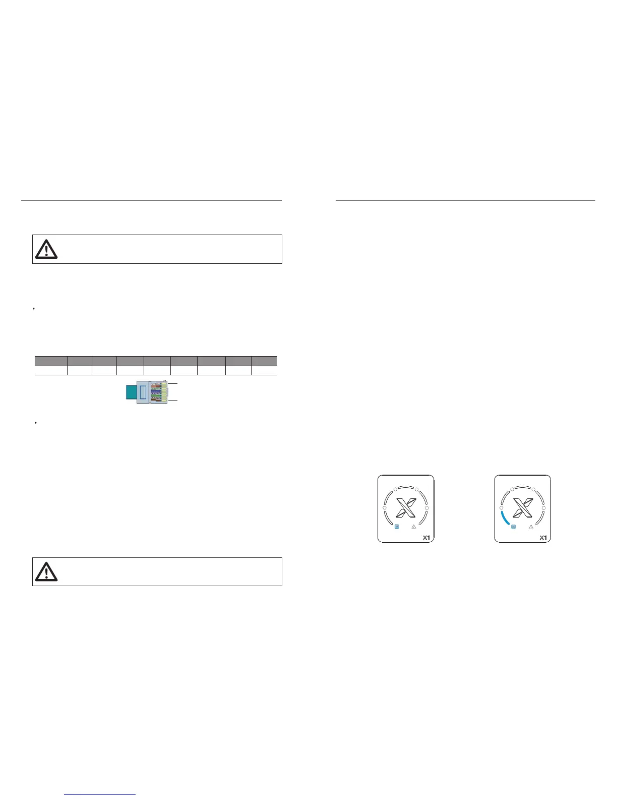
DRM is provided to give remote control with the optional accessory. The remote
control function provides a contact signal to operate the inverter. The pin
definition and the circuit connection show as below.
a) Make sure all the DC breaker and AC breaker are disconnected.
b) AC cable is connected to grid correctly.
c) All PV panels are connected to inverter correctly, DC connectors which are not
used should be sealed by cover.
a) Turn on switches of DC and AC side.
b) Inverter will start up automatically when PV panels generate enough energy.
Below is three different states when operating, which means inverter starting up
successfully.
- Waiting: Inverter is waiting to checking when output DC voltage from PV panels
is greater than 65V (lowest start-up voltage) but less than 100V (lowest operating
voltage). Under this mode, the blue light “a” is flickering, shown as figure (A).
- Checking: Inverter will check output environment automatically when DC
output voltage of PV panels. Under this mode, the blue light “a” is flickering, shown
as figure (A).
- Normal: Inverter begins to operate normally with blue light “a” on. Inverter will
work in MPPT mode when PV voltage is in the MPPT voltage range, inverter will
stop feedback to grid when PV power is not enough.
Under this mode, the blue light “a” is always on, light ”L1,L2,L3,L4,L5” represent the
output power. As shown in figure (B), the output power is 0%~20%".
a) Choose at least 1mm² wire. Trip the insulation from the wire ends.
b) Open the lid on the bottom of the inverter.
c) Insert the tripped wire into the hole of the terminal block.
d) Screw down the screws on the terminal block.
DRM
E.F.Alarm (optional)
Communication
Connection steps
1
8
Pin
Definition
1 2 3 4 5 6 7 8
DRM1 DRM2 DRM3 DRM4 3.3V DRM0 GND GND
5.6 Start the Inverter
5.6.1 Start the inverter after checking all below steps:
5.6.2 Start inverter
L1 L1
L2 L2
(A)
waiting/checking
(B)
Normal
L3 L3
L4 L4
L5 L5
1 1
a
a
b
b
2 2
3 3
4 4
5. Installation5. Installation
2322
If the updating process is paused for more than 3 minutes, please
reinsert the USB flash drive.
Note !
The updating process for ARM needs about 5 seconds and DSP needs about 3
minutes.
Direct functional earthing of system is not recommended.
Functional earthing via a resisitor is a safer option.
Note !
 Loading...