RS 485 is generally for inverter’s communication. System monitor should be
configured to realize one PC communicates with inverter at same time. Through
PC could get real time PV plants operating data.
The correspond relationship of the pins of RJ 45 and network cable color shows
as below.
Communication
RJ 45 Line NO.
T568B connection order
1
2
3
4
5
6
7
8
Cable Color
Whight orange
Orange
White green
Blue
White blue
Green
White brown
Brown
5. Installation5. Installation
Choose high-quality network cable, trip the insulation from the wire ends. For the
end use for the inverter, follow T568B order with press pliers to push into the 8-wire
RJ 45 crystal head. For the other end, follow the 2-wire RJ 45 crystal head to
connect with the RS 485 converter connector.
RS 485 converter connection
Connection steps
Cable Color
4
5
RS 485 Converter
A
B
Blue
White blue
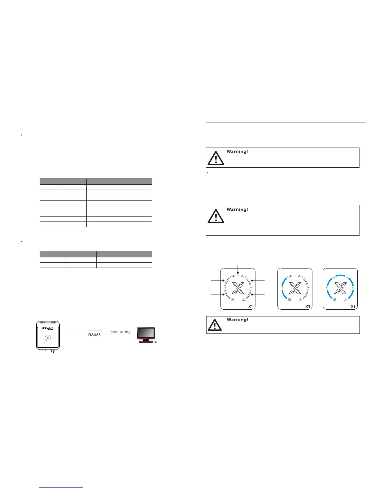
User can update the inverter system through a USB flash drive.
b) Make sure the DC switch is off and disconnect the AC with grid. Insert USB flash
drive into the “USB” port on the bottom of the inverter. Then turn on DC switch or
connect the PV connector, blue light “a” and red light “b” flash alternately for 10
times. Indicator light “1”, “2”, “3”, “4” are unlit.
c) About seconds later, the system will be updated automatically. During this 10
period, blue light “a” is always been on and red light “b” is unlit. Indicator light “L1”, ”L2”,
“L3”, “L4”,”L5” show the progress of system updating. Refer to figure (B1), it shows that
the updating process is half-finished. Once finished completely, it shows as figure
(B2).
a) Prepare a USB flash drive. Download the latest installation package named
“update.rar” from Solax website: www.solaxpower.com. And then extract it into
following directory:
USB for Updating
Make sure the directory is in accordance with above form strictly!
Do not modify the program file name and the capital letter can not
be changed to lower case! Or it may cause the inverter doesn’t
work anymore !
During updating, don’t switch off the DC switch or cut off the
external dc breaker!
Connection steps
1
2
3
4
X1
1
a
L1
L2
(A)
L4
L3
L5
b
2
3
4
(B1) (B2)
1 1
a a
b b
2 2
3 3
4 4
2120
Make sure the input voltage is more than 100V (in good illumination
condition). Or it may result in failing during updating.
“update\ARM\618.000 _X1AIR_ARM_Vx.xx_xxxxxxxx.usb”;76.00
“update\DSP\618.00070.00_X1AIR_DSP_Vx.xx_xxxxxxxx.hex”.
 Loading...