5.6 Run the inverter
a) Check that device is fixed well on the wall.
b) Make sure all the DC breakers and AC breakers are disconnected.
c) AC cable is connected to grid correctly.
d) All PV panels are connected to inverter correctly, DC connectors which
are not used should be sealed by cover.
e) Turn on the external AC and DC connectors.
f ) Turn on the DC switch to the “ON”position.
Start inverter after checking all below steps:
Start inverter
Inverter will start automatically when PV panels generate enough energy.
Check the status of LED indication and LCD screen, the LED indication should be
blue and the LCD screen should display the main interface.
If the LED indication is not blue, please check the below:
- All the connections are right.
- All the external disconnect switches are closed.
- The DC switch of the inverter is in the “ON” position.
Warning!
Power to the unit must be turned on only after installation
work has been completed. All electrical connections must
be carried out by qualified personnel in accordance with
legislation in force in the country concerned.
Note!
Please set the inverter if it is the first time to start up.
Above steps are for the regular start of the inverter. If it is the first
time to start up the inverter, you need to setup the inverter.
6. Operation Method
6.1 Control panel
Below is the three different states when operating, which means inverter starting
up successfully.
Waiting: Inverter is waiting to checking when DC input voltage from panels is
greater than 140V(lowest start-up voltage) but less than 180V(lowest operating
voltage).
Checking: Inverter will check DC input environment automatically when DC
input voltage from the PV panels exceeds 180V and PV panels have enough
energy to start inverter.
Normal: Inverter begins to operate normally with blue light on. Meanwhile
feedback energy to grid, LCD displays present output power.
Enter the setting interface to follow the instructions when it is first time to start
up.
B
C
D
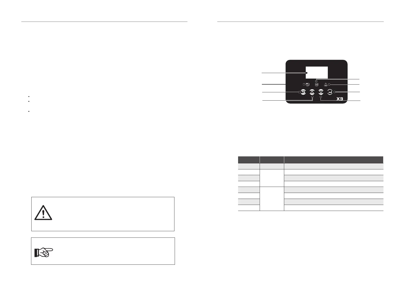
Object Name Description
F
G
H
E
Indicator
LED
Function
Button
Blue:The inverter is in normal state.
Red:The inverter is faulty.
Yellow:The inverter is in communication.
Down button: Move cursor to downside or decrease value.
ESC button: Return from current interface or function.
OK button: Confirm the selection.
Up button: Move cursor to upside or increase value.
A
LCD Screen
Display the information of the inverter.
2828 29
Installation Operation Method
C
D
F
G
A
B
H
E

 Loading...


