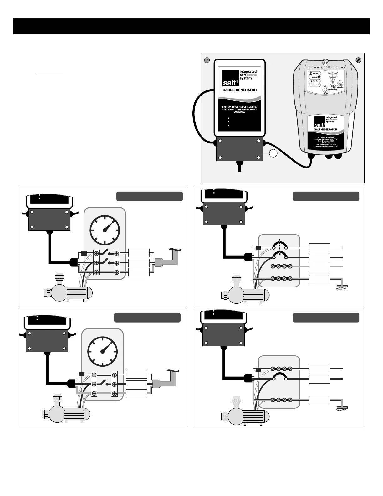
Wiring the Power Supply Box
1. Connect the green wire to the Ground lug of the timer.
2. Connect the black Load wire from the chlorine generator to Load 1 of the time clock.
3. If wiring a 240 Volt system, connect the white wire with black shrink to Load 2 of the time clock. If wiring a 120 Volt
system, connect the white wire with black shrink to the Neutral lug on the timer and REMOVE the black shrink tube.
5
Install the Generator Assembly
Ground
L1
To circuit
breaker
panel
Timer
240V Pump
240V Install with Timer
L2
N
L1
Circuit Breaker
Panel
240V Install w/o Timer
L2
Ground
240V Pump
Ground
L1
To circuit
breaker
panel
Timer
120V Pump
120V Install with Timer
N
Circuit Breaker
Panel
120V Install w/o Timer
L1
Ground
120V Pump
N
1. The Generator Assembly must be mounted
vertically on a flat surface and a minimum of 5 ft
(1.5m) horizontal distance (or more, if local codes
require) from the pool/spa.
2. Locate a position for your Box within 8 ft of where
the Manifold Assembly will be installed
3. Do not block the four sides of the Control Box. Do
Not mount the system above a heater or inside a
panel or an enclosed area.
4. If possible, try to mount the Assembly out of direct
sunlight.
120/240 VAC
50/60 Hz
2.0/1.1 Amp
2
Wall Mounted Generator Assembly
120/240 VAC
50/60 Hz
2.0/1.1 Amp
JUNCTION
BOX
120/240 VAC
50/60 Hz
2.0/1.1 Amp
JUNCTION
BOX
120/240 VAC
50/60 Hz
2.0/1.1 Amp
JUNCTION
BOX
120/240 VAC
50/60 Hz
2.0/1.1 Amp
JUNCTION
BOX
JUNCTION
BOX
Connect as shown below
ELECTRICAL CONNECTIONS