7 LCB FITNESS BIKE
4
3
HANDLE
BAR
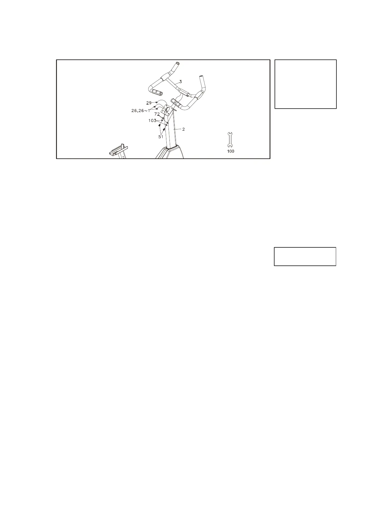
HARDWARE STEP 3
#51. 5/16” x 5/8”
Hex Head Bolt (2 pcs)
#72. 5/16” x 18 x 1.5T
Flat Washer (2 pcs)
#103. 5/16” x 1.5T
Split Washer (2 pcs)
1. Secure the Seat Handle Bar (3) onto the Console Mast (2) with the two
of Hex Head Bolts (51), two of Flat Washers (72) and two of Split
Washers (103) by using the 12/14mm Wrench (100).
2. Let the two of Hand pulse W/Cable Assembly (26) through the front of
hole on the Console Mast (2) and outside.
PLASTIC
PARTS
See page 8 for illustration
1. Insert the Computer Cable (29) and the two of Hand pulse W/Cable
Assembly (26,26~1) onto the Console Assembly (34).
2. Secure the Console Assembly (34) onto the Console Mast (2) with the
four of Phillips Head Screws (58) by using the Phillips Head Screw
Driver (93).
3. Secure the Front Stabilizer Cover (40) onto the Main Frame (1) with
the two of Phillips Head Screws (58) by using the Phillips Head Screw
Driver (93).
4. Install the Pedals (L)(R) (45)(46) onto the Crank Arms (16L)(16R) by
using the13/15mm Wrench (92).
5. Turn on the Brake Tension Knob (86) and put the Sliding Seat Mount
(7) on the Seat Slider (6).
6. Let the Brake Tension Knob (86) through The Flat Washer (71) , the
Seat Slider (6) , the Sliding Seat Mount (7) , go on Adjust the position
and tighten the Brake Tension Knob (86) with the Fix Plate (8).
7. Install the Seat (19) on the Sliding Seat Mount (7) by using the
12/14mm Wrench(100).
Apply the Cap Nut (78) onto the screw of the Brake Tension Knob (86)
and tighten.
HARDWARE STEP 4
#58. M5 x 12mm Phillips
Head Screw (6 pcs)