.12. .13.
4. Installation4. Installation
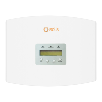
a. Refer to figure 4.16, the RS485 terminals for inverter and EPM are already assembled.
Tips:RS485 cable: preferred 0.5mm², max 1.0mm².
.
Figure 4.16 RS485 terminal
b. Refer to figure 4.16, connect communication cable between inverter with EPM, and
then measure the distance from EPM to inverter. Use proper cable for RS485
connection. (0.5mm²)
c. Follow step1 to assemble 2 connectors to each end of cable.
≈
Inverter 1 Inverter 2 Inverter n
Rs485 IN | OUT
Rs485 IN | OUT
Rs485 IN | OUT
Rs485term inal
EPM BOX
Figure 4.17 RS485 cable connection
+ to connect RS485 A
- to connect RS485 B
φ25.5
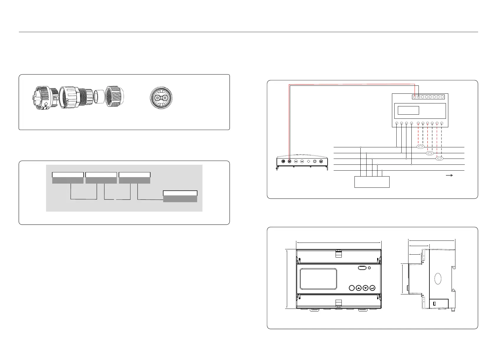
Connection between EPM and meter
EPM3-5G-PRO needs to connect to the RS485 communication of the meter to read and
display the power, voltage, and current data on the grid side.
Pre-made Cable in Meter Package
2-Pin Connector
L1 L2
L3
N PE
Load
INV L1
INV L2
INV L3
INV N
INV PE
Grid L1
Grid L2
Grid L3
Grid N
Grid PE
UaUb Uc N Ia* Ia Ib* Ib Ic* Ic
21 22 17
1819 20
A B
CT Arrow
Grid
Figure 4.18
4.3.3 Meter connection (only for EPM3-5G-PRO)
Wiring and installation of meter
1.Specification of electricity meter
1.1Dimension Drawings
126.5
69.5
31.5
19.5
88.2
45.4
unit:mm
Figure 4.19
CT1 /Mete r
GRI D Com munic ation C omm-I NVCT2 CT3
4.3.2 Make RS485 cable(COMM-INV port)