4. Installation4. Installation
1.3Wiring and Installing
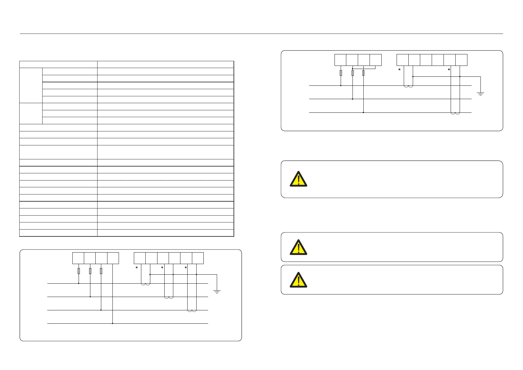
Ua Ub Uc N
Ia* Ia Ib* Ib Ic* Ic
A
B
C
N
Figure 4.20 Three phase four lines connect via CT
.14. .15.
1.2Dimension Drawings
Current
Reference voltage
Input current
Input voltage fluctuation
Consumption
Consumption
Accuracy class
Impedance
Accuracy class
3-110V, 3-400V, 3-480V, 3-66/115V, 3-230/400V, 3-277/480V
3-1(6)A
0-120%
<1VA(Single phase rated current)
<10VA(Single phase)
>2MΩ
Error±0.2%
Error±0.2%
3 phase 3 wires, 3 phase 4 wires
Power
Frequency
Energy
Energy pulse output
Switching input
Width of pulse
Pulse constant
Interface and communication
Range of communication address
Baud rate
Working temperature
Relative humidity
Altitude
Installation environment
Pollution degree
Active, reactive, apparent power, error±0.5℅
45~65Hz, Error±0.2%
Active energy(Accuracy class:0.5, 1), reactive energy(Accuracy class 2)
1 active optocoupler output, Resistive load(Voltage is not more than 24V,
current is not more than 5mA)
1 optocoupler input,Maximum allowed voltage: ~ 220V, OVC Ш
80±20ms
400imp/kWh
RS485:Modbus RTU
Modbus RTU:1~ 247;
1200bps~19200bps
-25℃~+55℃
≤95℅(No condensation)
≤ 2000m
Indoor use
Class 3
Voltage
Specification
Figure 4.21 Three phase four lines connect via CT
Ua Ub Uc
Ia* Ia Ib* Ib Ic* Ic
Un
A
B
C
To detect the backflow power, the CTs need to be installed at the PCC
(Point of Common Coupling), instead of the load branch circuit.
NOTE:
For three phase system, CT must be installed on U,V and W with correct
sequence, otherwise EPM can not detect the correct data.
“The CT cable outer diameter is 6.5mm-7.5mm, cross-sectional area 1.5mm²”.
a. Switch off the main switch, disconnect the line cables.
b. Insert the cables through the CT, make sure the P1 on CT is towards grid and P2 is
towards the inverter.
c. Reconnect the line cables.
4.3.4 Connect and fix the CT
NOTE:
If the CT is installed in the wrong direction, the EPM can't work normally.
NOTE:
The CT must be grounded on the secondary side.