Page 8
SOLLATEK INTELLIGENT CONTROLS
4. INSTALLATION
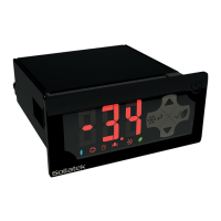
4.1 DIMENSIONS AND PANEL CUT-OUT
4.2 PANEL MOUNTING
• Cut a rectangle aperture in the panel of the cooler where the display is to be located as per the panel cut diagram.
Ensure the aperture is free of burrs and sharp edges.
Note: The Maximum panel thickness must not exceed:
• Front mount its 1.6mm max with gasket and 3.6mm max without gasket.
• Side mount clips its 6.6mm max with gasket and 8.6mm max without gasket.
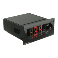
4.2.1 FRONT MOUNTING
• Remove the Front fascia from the front of the JEA by pulling it o.
• Insert the JEA into the front of the panel.
• Using a screwdriver tighten the bottom screw. After turning 90
o
the catch will come out of it’s slot and press onto
the panel. Tighten the screw until the front panel is secure. Repeat the same operation for the top screw.
Note: Ensure the JEA is securely tted to the cooler and DO NOT over tighten the screw.
• Push the faceplate back onto the JEA.
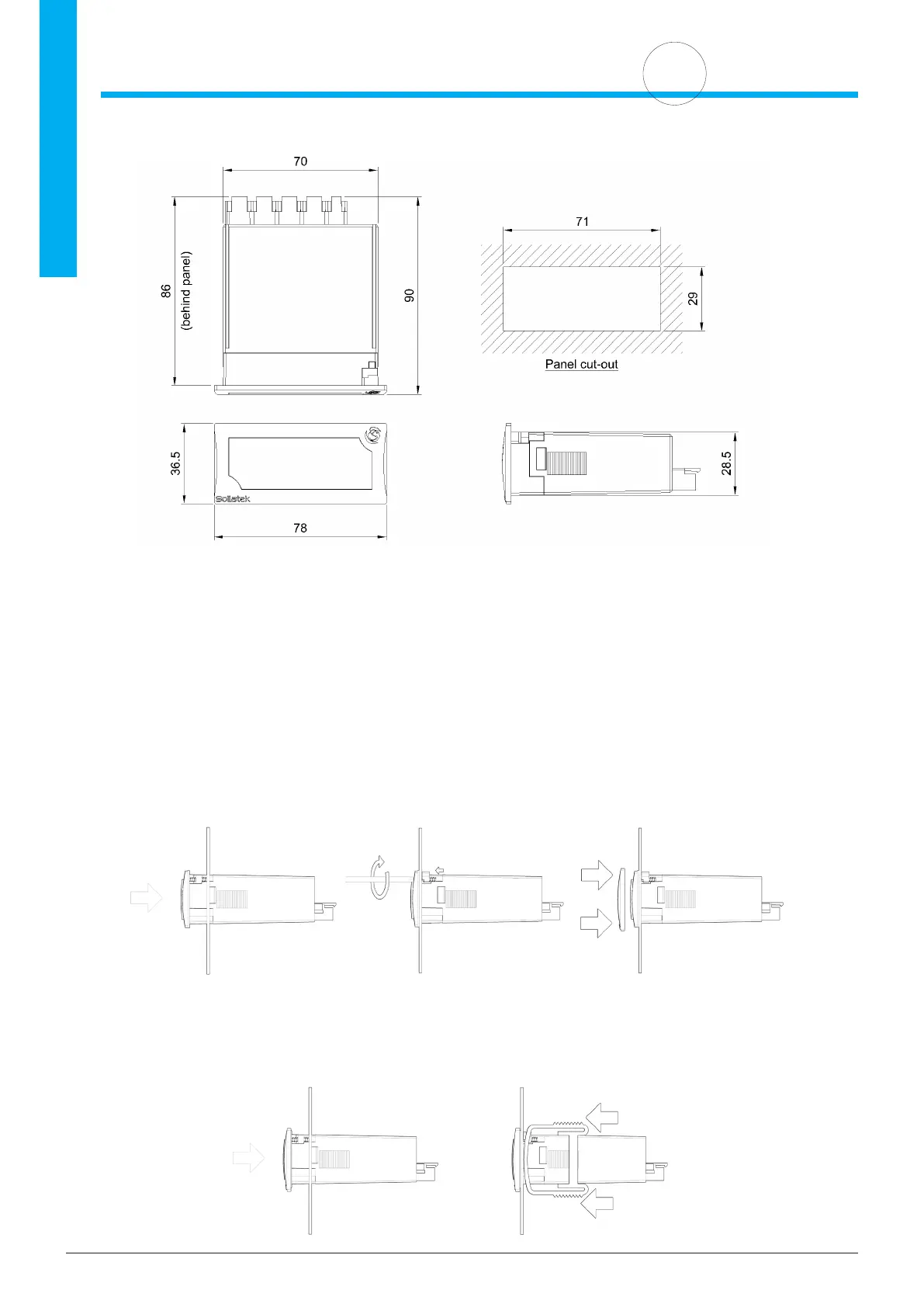
4.2.2 REAR MOUNTING
• Insert the JEA into the front of the panel.
• Secure the JEA by sliding one of the side clips into the guides on top and bottom of the body until compressing it
against the panel. Repeat the same operation for the other side
Note: Ensure the clips are securely attached to the JEA and are tight against the panel.
 Loading...