Figure 3
10
www.solo-tester.com
Cartridge
Flashing Red: Consumable low
Solid Red: Consumable empty
Battery
Flashing Red: Consumable low
Solid Red: Consumable empty
|
|
|
|
|
|
|
|
|
|
|
|
|
|
|
|
|
|
|
|
Using
Solo 365
4
• Do not block air vents during use.
• Use only cartridges and batteries specied
by the manufacturer.
NOTE: A Solo 101 extension pole can extend the Solo
100 and 108 telescopic poles, or may be used separately.
For further information on the correct use of poles, see
“Instructions for Solo Poles” document in the support
section of solo-tester.com
http://www.solo-tester.com/site/support
/product_manuals/
11
www.solo-tester.com
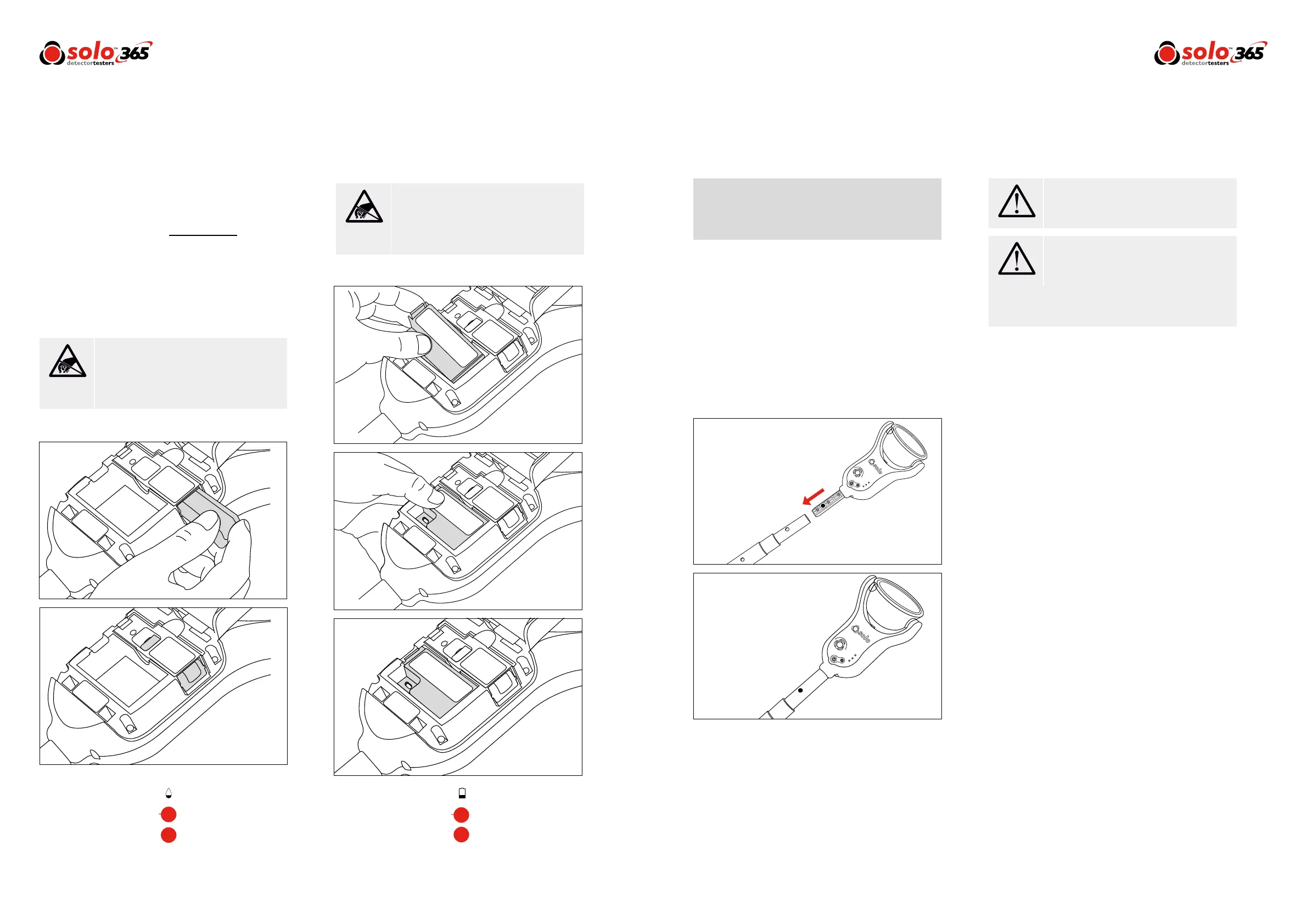
Figure 4
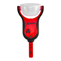
3.3 Inserting the Smoke Cartridge
• Remove cartridge from bag.
• Do not insert smoke cartridge until generator has
been fully tted into the main unit. See installing the
Generator section 3.2 (Page 9).
• Slide cartridge completely into generator housing
following the guide rails (Fig. 2).
• Once the cartridge is inserted into the generator do
not remove it until indicated that a
replacement is necessary. Do not re-use old
cartridges.
• Empty cartridges may be returned to the
manufacturer via the reseller for environmentally
friendly disposal to comply with WEEE (Waste
Electrical & Electronic Equipment) Regulations.
3.4 Inserting the Battery
• Once the battery is charged clip the battery pack into
the battery compartment. (Fig. 3).
• Do not force the battery into place.
• Close the back cover.
Do Not Touch
Do Not Touch
Caution
Warning
Do not touch the contacts on the PCB on the
cartridge. Static electricity may cause damage
and contamination of the contacts must be
avoided.
Do not touch the contacts on the battery.
Static electricity may cause damage and
contamination of the contacts must be
avoided.
No more than 3 Solo 101 extension poles
should be used at the same time.
When working at height it is recommended
that a competent person carries out a suitable
risk assessment. This will identify any risk to the
user and/or the environment and hence any
need for Personal Protective Equipment.
Figure 2
4.1 Attaching Solo 365 to Solo Access Poles
Solo 365 is designed for use with the Solo range of access
poles. (purchased separately). The product is not
compatible with alternative access poles.
• Take the Solo access pole and press down the locking
button on Solo 365. Align it with the location hole and
push the Solo 365 handle further into the pole until
the button springs up through the hole. Twist to lock.
(Fig. 4)
4.2 Powering on Solo 365
With the generator, cartridge and battery securely tted and
the back covered closed, the unit can now be powered on.
Power the unit on by holding down the power button for
3 seconds.
NOTE: After replacing a generator and powering on, a
‘purge cycle’ will run. During this the sound of the pump
operating may be heard. This will last for approximately a
few seconds after which, the unit will be ready for use.
The unit is functioning correctly if the status indicators are
ashing green slowly. If the status indicators are not
ashing green consult the indicator LED section (Page 12).
NOTE: If Solo 365 has been left unused for a period of
time then a manual purge may be required (Section 4.9).