B2)FLAIL HOLDER ROTOR CONTROL CABLE ( FIG. 5 REF. B)
Make sure that there is no play between the upper end of the cable and the ad-
justment screw. If there is, or if the cable has stretched, restore to ideal position
using the relative adjustment screw.
If adjustment using the relative screw proves ineffective, the belts, and hence the
engine mounting, must be adjusted. To perform this operation refer to section 14 C
“ BELT REPLACEMENT AND ADJUSTMENT” of this manual.
WARNING
After having made the adjustments as described above, check that the flail
rotor brake is still working properly, stopping roller movement immediately.
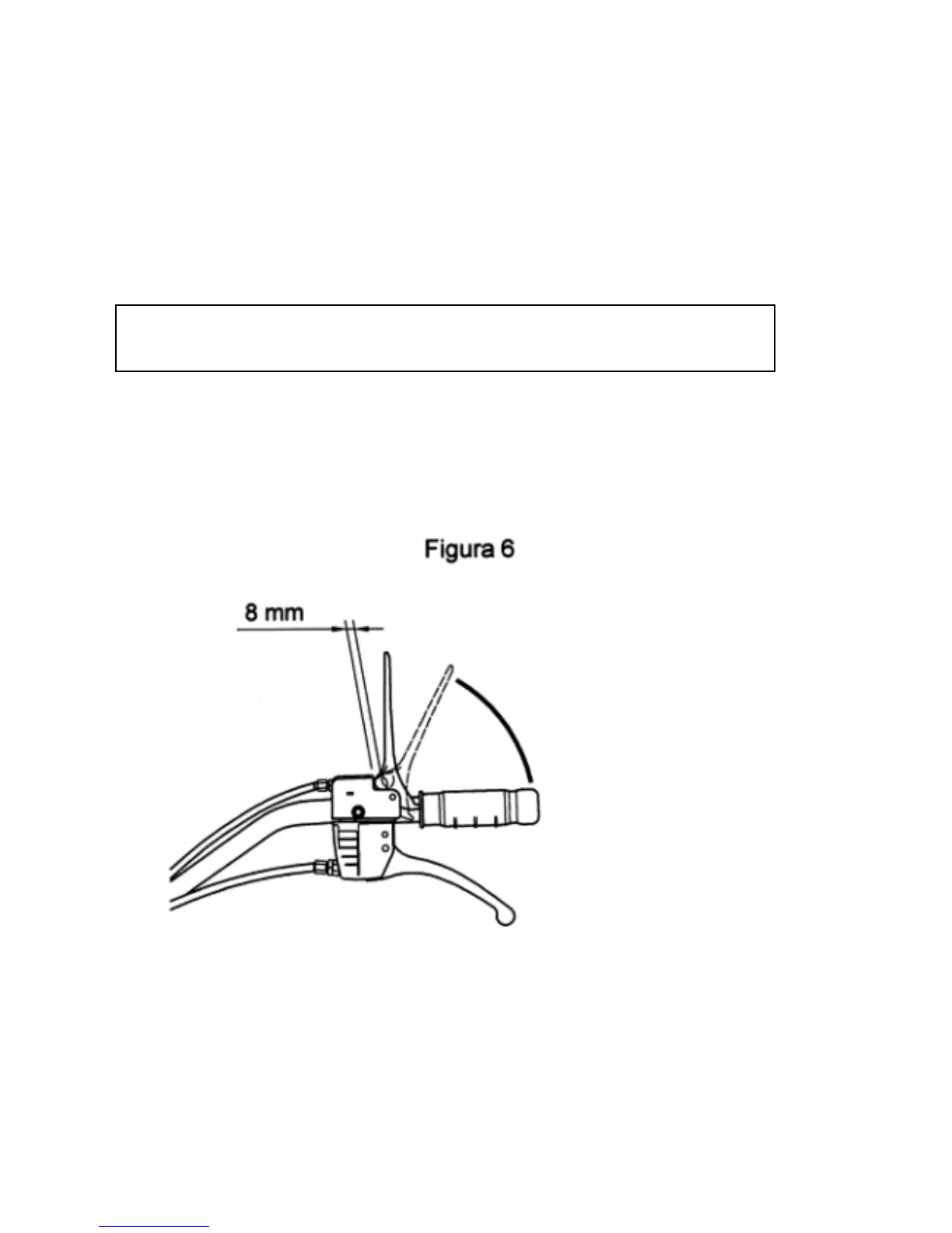
This check can also be performed using the flail holder rotor control lever. In fact, if
when lowered a certain resistance is felt immediately, remaining constant to the
end of its stroke, it is caused by the fact that the brake cable does not have the
necessary play for its operation. Figure 6 shows the optimum working condition.
Hence the first part of the lever stroke (broken line) presents a lower resistance
compared to that of the second part (solid line).
Figure 6
Should it be necessary to restore it to ideal condition adjust the belts as described
in section 14 C ”BELT REPLACEMENT AND ADJUSTMENT” of this manual and if
this adjustment is insufficient use the adjustment device on the flail rotor brake
shown in fig. 7: